Lighting / Fixtures
User Manual for Bell Lighting 09083V2 Emergency Exit Sign
Quick guide for the Bell Lighting 09083V2 Emergency Exit Sign. Includes installation wiring diagrams, testing procedures, LED status indicators, and maintenance instructions.
Table of contents
Manual images
Click an image to enlargeQuick guide from the manual
This document provides installation and maintenance instructions for the Bell Lighting 09083V2 Emergency Exit Sign. Important: This equipment must be installed by a competent electrician in accordance with current IEE wiring regulations BS7671:2018. Before initial use, the unit requires a continuous charge of 36 hours to ensure the battery is fully charged.
Specifications
- Input Voltage: AC220-240V 50/60Hz
- Wattage: 3W
- Battery: LiFePO4 3.2V 1500mAh
- Emergency Duration: More than 3 hours
- Operating Temperature: 0-40°C
- Surface Brightness: ≥ 200 cd/m2
Installation
1. Open the fitting by inserting a small screwdriver into the two tabs.
2. Drill the fixing holes in the base and feed the mains cable into the fitting.
3. Ensure the battery is connected to the main PCB.
4. Refasten the cover.
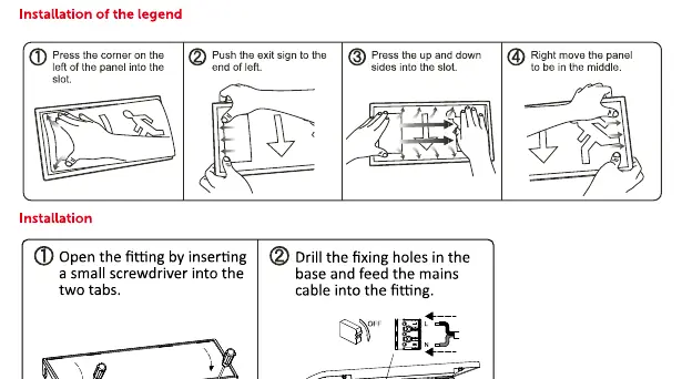
5. Install the legend by pressing the corner on the left of the panel into the slot, pushing the sign to the end of the left, pressing the up and down sides into the slot, and moving the panel to be in the middle.
Wiring
The unit supports three wiring configurations:
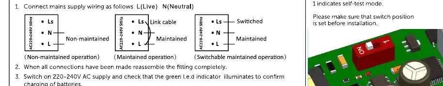
- Non-maintained operation: Connect Ls and N.
- Maintained operation: Connect L, N, and Link cable.
- Switchable maintained operation: Connect L, N, and Switched Ls.
Testing and Operation
The unit features a self-test function. The test button on the right side of the fitting allows for manual testing:
- Press for approx 1 second: Emergency mode for 1 second.
- Press for approx 5 seconds: Function test for 30 seconds.
- Press for approx 7 seconds: 3-hour duration test.
- Press for approx 10 seconds: End the duration test.
LED Status Indicators
The green LED indicates the status of the fitting:
- Green solid: Mains on / No fault.
- Green flash: Slow flash (Function test for 2 minutes), Fast flash (3-hour duration test).
- Red flash: 1 Flash cycle (Battery fault), 2 Flash cycles (Lamp fault), 3 Flash cycles (Duration test fault).
Maintenance
Routine testing is required to ensure safety:
- Once a day: Visual inspection of battery charge LED.
- Once a month: Each unit should be energized from its battery for adequate time to ensure, by simulation of a failure of the normal lighting supply, that the emergency mode is functioning correctly.
- Once each year: All units should be placed into emergency mode and checked that the duration provided by the battery meets the specified time period.
Manufacturer information
BELL Lighting
Practical help
Common problems
Red flash on LED
1 Flash cycle indicates a battery fault; 2 Flash cycles indicate a lamp fault; 3 Flash cycles indicate a duration test fault.
Unit not working in emergency mode
Ensure the battery is connected to the main PCB and the unit has been charged for 36 hours.
Ambient temperature too high
Ensure the room temperature does not exceed 35°C to prevent damage.
Before use
- Ensure mains supply is switched off before installation.
- Verify the switch on the PCB is set correctly before installation.
- Ensure adequate free air ventilation around the fitting.
- Check that the ambient temperature does not exceed 35°C.
- Perform a 36-hour continuous charge before initial use.
Specs in practice
- Emergency duration
- The unit will provide light for more than 3 hours during a power failure.
- Operating temperature
- The unit is designed to operate safely between 0°C and 40°C.
Images and diagrams
- Wiring diagrams show connections for Non-maintained, Maintained, and Switchable maintained operations.
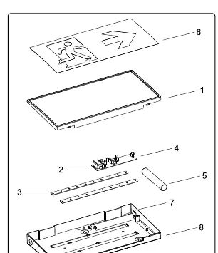
- Exploded view shows assembly of cover, terminal block, LED, PCB, battery, and legend.
Model compatibility
- Must be installed by a competent electrician.
- Tests must be carried out in accordance with EN 50172:2004.
- The light source of this luminaire is not replaceable; the whole luminaire must be replaced at end of life.

Manual page author
Emily Carter
User documentation editor
Prepares concise manual descriptions and highlights the most useful setup, operation, and maintenance information for readers.