Lighting / Fixtures
Installation Instructions for BELL Lighting 11370V2 LED Downlight
A comprehensive installation guide for the BELL Lighting 11370V2 Firestay CCT LED Downlight. Includes step-by-step mounting instructions, wiring diagrams, configuration settings for color temperature and wattage, and safety requirements.
Table of contents
Manual images
Click an image to enlargeImportant Information
This product must be installed by a qualified electrician in accordance with current IEE wiring regulations (BS7671:2018) and local building control. The light source is not replaceable; the entire luminaire must be replaced when it reaches the end of its life. The ambient room temperature should not exceed 30°C.
Installation Steps
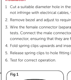
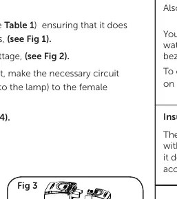
- Prepare the ceiling: Cut a suitable diameter hole in the ceiling (68-70mm). Ensure the area is free from electrical cables, water/gas pipes, or ceiling joists.
- Adjust settings: Remove the bezel to access the switches. Select your preferred color temperature (2700K, 3000K, 4000K, or 6000K) and wattage (4W or 6W).
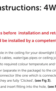
- Wiring: Wire the female connector (included in the package) to the circuit. Perform necessary circuit tests. Connect the male connector (attached to the lamp) to the female connector, ensuring they are fully 'Clicked' together.
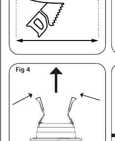
- Insert fitting: Fold the spring clips upwards and insert the fitting into the prepared hole.
- Secure: Release the spring clips to lock the fitting in place.
- Test: Perform a final test for correct operation.
Wiring and Configuration
The wiring requires connection to Live (Brown), Earth (Yellow/Green), and Neutral (Blue). The bezel can be changed by twisting and locking it onto the fitting. This unit is IC Rated (Insulation Coverable), meaning it is designed for use with insulation material and does not require extra IC cage accessories.
Technical Specifications
- Model: 11370V2
- Cutout Diameter: 68-70mm
- Color Temperatures: 2700K, 3000K, 4000K, 6000K
- Wattage Options: 4W / 6W
- Compliance: BS7671:2018, EN 50172:2004
Manufacturer information
BELL Lighting
Practical help
Common problems
Light does not turn on
Verify that the male and female connectors are fully clicked together and that the circuit is live.
Bezel is loose
Ensure the bezel is properly twisted and locked onto the fitting.
Before use
- Ensure power is switched off at the mains before starting installation.
- Verify the ceiling cutout diameter is between 68-70mm.
- Check for obstructions like cables, pipes, or joists before cutting.
- Confirm the ambient room temperature will not exceed 30°C.
- Ensure the installation complies with BS7671:2018 regulations.
Images and diagrams
- Fig 1: Ceiling cutout preparation.
- Fig 2: Bezel removal and CCT/Wattage adjustment.
- Fig 3: Connector wiring and locking mechanism.
- Fig 4-5: Spring clip installation procedure.
- Fig 6: Bezel twist and lock mechanism.
Model compatibility
- Must be installed by a qualified electrician.
- Complies with IEE wiring regulations BS7671:2018.

Manual page author
Michael Turner
Technical manual editor
Reviews PDF manuals for structure, safety notes, and practical product details so readers can find the right information quickly.