Automotive / Suspension Kits
Installation Instructions for Belltech 150201BK Suspension Lift Kit
A comprehensive installation guide for the Belltech suspension lift kit (models 150201BK and 150203BK). This manual provides step-by-step procedures for front and rear lift installation, tool requirements, and safety warnings for 2007-2018...
Table of contents
Manual images
Click an image to enlargeImportant Installation Information
This document provides installation instructions for the Belltech suspension lift kit, compatible with 2007-2018 Chevrolet Silverado and GMC Sierra 2WD/4WD vehicles. Before beginning, verify that all hardware listed in the parts list is included in the kit. Do not start the installation if any parts are missing. It is highly recommended to have an assistant available during the process.
Recommended Tools
- Properly rated floor jack and support stands
- Wheel chocks
- Torque wrench (up to 200 ft/lbs)
- Standard and Metric socket wrench set
- Standard and Metric wrench set
- Tape measure
- Dead blow hammer
- Marking pen
- Safety glasses
- Reciprocating saw with metal cutting blades
Kit Preparation
Before starting, measure the hub-to-fender height for all four corners of the vehicle to compare with the final results. Park the vehicle on a smooth, level surface, activate the parking brake, and block the rear wheels. Ensure the transmission is in 1st gear (manual) or Park (automatic). Use support stands under the frame rails; do not rely solely on a jack.
Front Removal and Installation
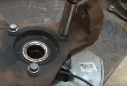
1. Disassembly: Use a vehicle hoist if available, or jack up the front and place on support stands. Remove wheels and factory under paneling. Disconnect the sway bar, tie-rod ends, brake lines, ABS sensor wires, and brake calipers. Remove the rotors, axle nut, and upper/lower ball joint nuts to separate the spindle. Uninstall the strut.
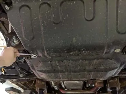
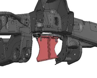
2. Differential and Crossmember: Remove the CV axle, lower control arms, and OEM gravel guards. Disconnect electrical connections and the driveshaft from the differential. Remove the crossmember. Trim the area marked in the instructions for the front crossmember installation and the rear driver's side mount if necessary.
3. Installation: Install differential drop spacers with the tapered end toward the rear. Reinstall the differential, crossmembers, and lower control arms. Install CV axles with spacers. Reassemble the spindle, ball joints, and brake components. Install the compression arm brackets and compression arms.
Rear Lift Installation
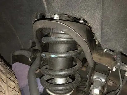
1. Disassembly: Jack up the rear of the vehicle from the differential and place on jack stands. Remove wheels and factory shock absorbers. Remove factory u-bolts, carrier plates, and lift blocks. Lower the axle carefully.
2. Installation: Install the new lift blocks on the spring pad with the flat part on the spring and the tapered end toward the front. Align the center pin. Install the new u-bolt hardware and tighten in a crossing pattern. Install the new shock absorbers in factory locations. Reattach brake lines and harness, ensuring there is enough slack. Reinstall wheels and lower the vehicle.
Safety Warnings
- DO NOT work under a vehicle supported only by a jack. Always use secure support stands.
- DO NOT drive the vehicle until all work is completed and checked.
- DO NOT use wheel ramps during this installation.
- Always wear appropriate safety equipment, including eye, face, and hand protection.
- Torque all hardware to the specified values provided in the manual.
Practical help
Common problems
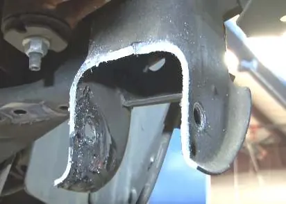
Tie rod end interference
Cut 1 inch from the end of the inner tie rod to allow for proper alignment.
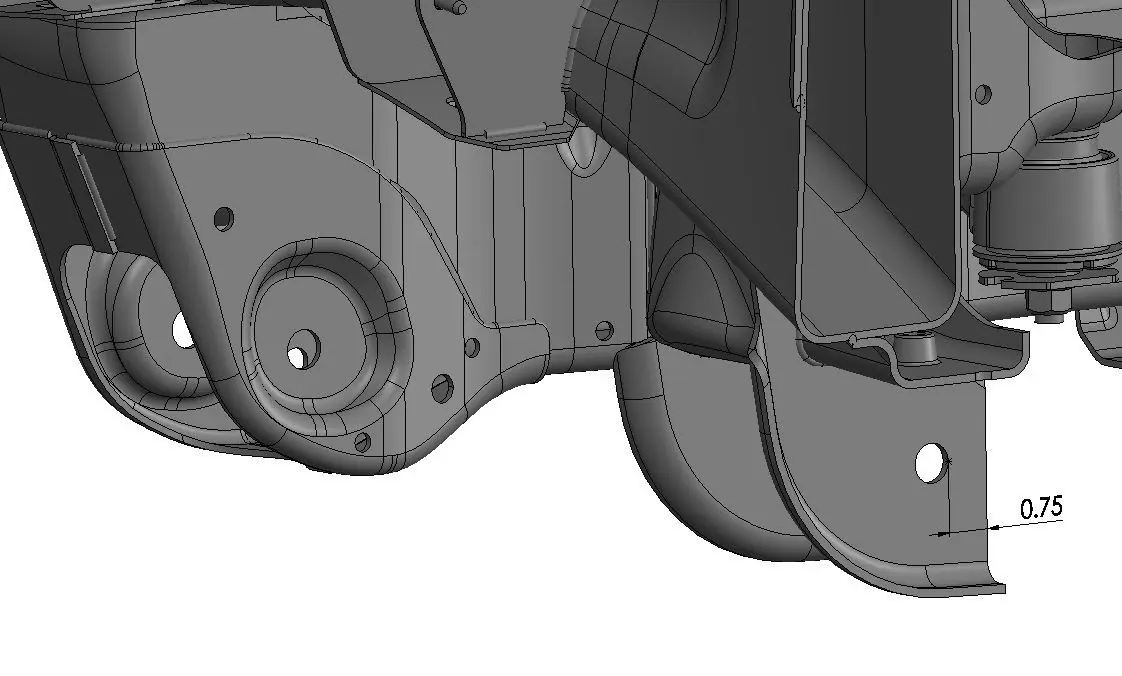
Crossmember interference with differential
Measure 3/4 inch from the edge of 'HOLE: A' and mark a vertical line to cut the crossmember (required for rear driver's side mount).
Ball joint spinning during removal
Use a 10mm wrench to hold the ball joint while removing the nut.
Before use
- Verify all hardware listed in the parts list is present.
- Ensure vehicle is on a smooth, level concrete or asphalt surface.
- Confirm you have a properly rated floor jack and support stands.
- Measure hub to fender heights before starting.
- Have an assistant available for the installation.
Specs in practice
- Crossmember Torque
- 130 ft-lb
- Ball Joint Torque
- 85 ft-lb
- Axle Nut Torque
- 180 ft-lb
- Outer Tie Rod Torque
- 65 ft-lb
- Sway Bar End Link Torque
- 35 ft-lb
Images and diagrams
- Photos 1-9: Front suspension disassembly steps.
- Photos 10-14: Differential and crossmember removal/trimming.
- Photos 16-20: Differential drop and crossmember installation.
- Photos 21-26: Spindle and compression arm installation.
- Photos 27-30: Rear lift block and shock absorber installation.
Model compatibility
- Fits 2007-2018 Silverado / Sierra 2WD / 4WD.
- 150201 fits Cast Aluminum / Stamped Steel UCA.
- 150203 fits Cast Steel UCA.

Manual page author
Emily Carter
User documentation editor
Prepares concise manual descriptions and highlights the most useful setup, operation, and maintenance information for readers.