Automotive / Suspension Kits
Installation Guide for Belltech 150220 Lift Kit
Step-by-step installation guide for the Belltech 150220 lift kit for GM 1500 SUV (2021+). Includes safety warnings, required tools, removal and installation procedures, and torque specifications.
Table of contents
Manual images
Click an image to enlargeQuick guide from the manual
This guide provides instructions for installing the Belltech 150220 lift kit on GM 1500 SUV vehicles (2021+). Before beginning, verify all parts against the kit contents list. The installation requires 4-6 hours plus alignment and should be performed by a qualified mechanic. Always use proper safety equipment and support stands; never work under a vehicle supported only by a jack.
Installation Preparation
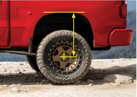
Before starting, measure the hub to fender heights for your vehicle and record them in the provided before section. Measure vertically from the center of the wheel to the inner edge of the fender. You will need a floor jack, ratcheting socket set, hammer, flat head screwdriver, support stands, wheel chocks, metric wrench set, tape measure, paint pen, safety glasses, a high-quality spring compressor, and a torque wrench up to 200lbs.

Jacking, Supporting, and Preparing the Vehicle
- Park on a smooth, level surface and block the rear wheels.
- Ensure the transmission is in PARK (automatic) or 1st gear (manual) and activate the parking brake.
- Loosen front wheel lug nuts.
- Lift the front of the vehicle 6-8 inches off the ground.
- Place support stands in factory-specified locations and lower the vehicle onto them.
- Remove the front wheels.
Front Removal
Follow these steps to remove the factory suspension components:
- Remove the tie-rod nut using a 21mm wrench. Use a dead blow hammer to dislodge the tie-rod end.
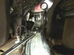
- Support the lower control arm with a jack and loosen the control arm bolts.
- Mark the settings on the eccentric washers for alignment.
- Remove the ABS sensor wire from the plastic clip and the bracket from the control arm.
- Disconnect the sway bar from the end links using 18mm and 9mm wrenches.
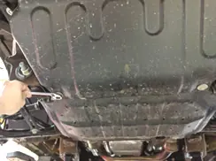
- Remove the lower shield (13mm wrench) and the axle nut (36mm socket).
- Remove the upper ball joint (18mm wrench).
- Separate the upper control arm from the spindle by striking the spindle on the designated bosses. Support the spindle to prevent it from drooping too far.
- Remove the top strut nuts (18mm wrench) and the bottom strut hardware (15mm socket) to remove the strut.
- Remove the upper control arm using a 21mm or 24mm socket and 21mm wrench.
Front Installation
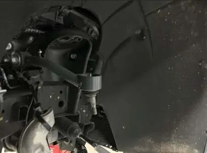
- Install the Belltech control arms using OEM hardware. Ensure the ball joint mounting ring is level and torque to 120 ft-lbs.
- Perform the front strut installation referencing the separate strut/coilover assembly instructions.
- Re-install spindles and reattach the upper ball joint nut (18mm wrench).
- Replace the axle nut (36mm socket).
- Install the Belltech skid plate using the same holes as the plastic shield. Tighten hardware to 40 ft-lbs using a 13mm socket.
- Reconnect the anti-sway bar, ABS sensor wire, and control arm bracket.
- Replace control arm bolts and realign based on previous markings. Torque lower control arm bolts once the vehicle is on the ground.
- Replace the tie-rod nut, install wheels, and lower the vehicle.
Finalizing the Installation
Re-install the wheels, tighten lug nuts, and remove support stands. Lower the vehicle to the ground and torque the lug nuts to manufacturer specifications. Check that all components and fasteners are properly installed and torqued. Perform a final check of all tasks in the Before Driving Your Vehicle section.
Kit Contents
The kit includes:
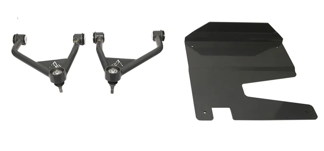
- Control Arm LH (150212-100L)
- Control Arm RH (150212-100R)
- Hardware Kit (150212-777)
- Skid Plate (150212-108-992)
- Hardware includes M10 x 1.50 - 70mm bolts, Nylock nuts, and Loctite 271 Red.
Practical help
Common problems
Ball joint slipping during tie-rod removal
Use a 10mm wrench to hold the ball joint while removing the nut.
Axle does not move freely
Tap the locating hole on the front axle.
Upper control arm under tension during removal
Support the spindle by running wire through the top ball joint boss and a supportive spot on the frame.
Before use
- Verify all components listed on the parts list are present in the kit.
- Measure hub to fender heights before starting.
- Ensure vehicle is on a smooth, level surface.
- Have a qualified assistant available.
- Ensure you have a high-quality spring compressor and torque wrench.
Specs in practice
- Control arm torque
- 120 ft-lbs
- Skid plate hardware torque
- 40 ft-lbs
- Installation time
- 4-6 hours plus alignment
Images and diagrams
- Hub to fender measurement: Measure vertically from the center of the wheel to the inner edge of the fender.
- Control arm installation: Ensure the ball joint mounting ring is level.
Model compatibility
- Fits GM 1500 SUV 2WD/4WD 2021+.
- Ride heights vary by kit: 150220TP/150220TPS (3.5-4.5 inches), 150220HK (3-4 inches).

Manual page author
Emily Carter
User documentation editor
Prepares concise manual descriptions and highlights the most useful setup, operation, and maintenance information for readers.