Automotive / Suspension Kits
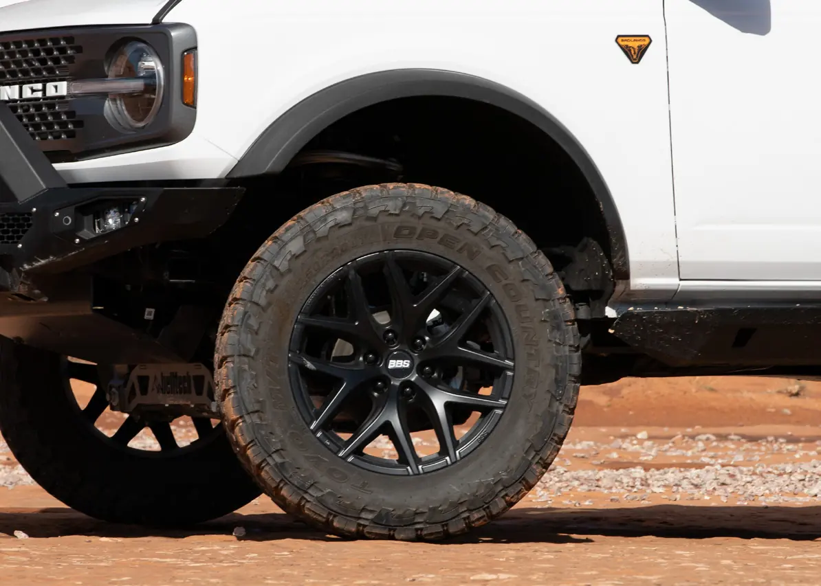
Installation Guide for Belltech 152600HK Lift Kit
Comprehensive installation guide for the Belltech 152600HK lift kit for Ford Bronco 4WD (2021+). Includes step-by-step instructions for front and rear suspension removal and installation, torque specifications, and safety warnings.
Table of contents
Manual images
Click an image to enlargeQuick guide from the manual
This installation guide provides instructions for the Belltech 152600HK lift kit designed for the Ford Bronco 4WD (2021+). The installation is complex and requires 10-12 hours plus alignment. Safety Warning: Never work under a vehicle supported only by a jack; always use properly rated support stands. Proper use of safety equipment, including eye and hand protection, is mandatory.
Installation Preparation
Before beginning, measure the hub to fender heights and record them in the provided sections for comparison after installation. Ensure all components listed in the parts list are present before starting. Recommended tools include a floor jack, ratcheting socket set, hammer, reciprocating saw/angle grinder with cutoff discs, support stands, wheel chocks, metric wrench set, tape measure, paint pen, safety glasses, metal file, sandpaper, and black spray paint. Specialty tools required include a high-quality spring compressor, torque wrench (up to 200 ft lbs), ball joint separator, ball peen hammer, and center punch.
Front Suspension Removal
The removal process involves several steps:
- Remove the front skid plate.
- Detach the front sway bar assembly.
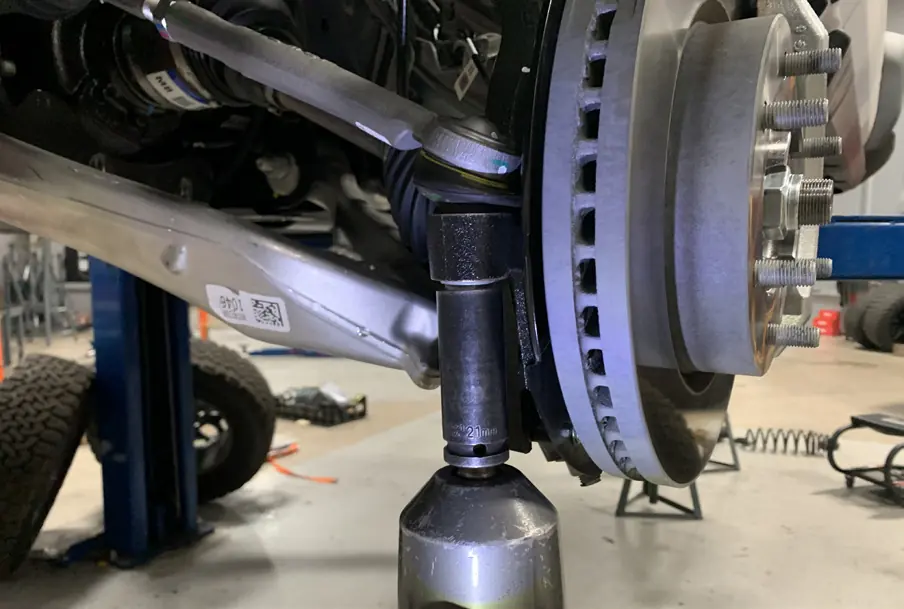
- Remove the steering tie rod end nut and detach the tie rod end from the spindle.
- Detach the wheel speed sensor and the front ABS/brake line bracket.
- Remove the brake caliper and rotor.
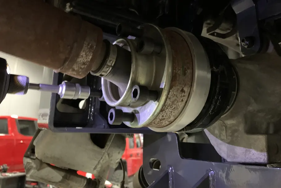
- Remove the CV axle nut and dislodge the axle.
- Detach the upper and lower ball joints from the spindle.
- Remove the hub and backing plate from the OEM spindle to mount onto the new Belltech spindle.
- Remove the strut assembly.
- Remove the lower control arms after marking the alignment cams.
- Disconnect hoses and connectors from the front differential, then remove the front drive shaft and the differential itself.
- Cut the rear cross member according to the marked lines (reference figures 1 and 2 in the manual) and smooth the edges.
- Grind the small lobe near the rear upper mounting holes on the differential for clearance.
- If applicable, cut the small aluminum protrusion on the back of the power steering rack.
Front Suspension Installation
Installation is performed in the reverse order of removal:
- Install the Belltech front skid plate and cross members.
- Raise the differential into place and install the rear differential mount plate.
- Ensure a minimum of 5mm clearance between the differential and the frame/steering rack.
- Install the Belltech drive line spacer.
- Install the new Belltech spindle onto the ball joints (Torque lower ball joint nut to 85 ft lbs, upper to 46 ft lbs).
- Reattach brake lines, wheel speed sensors, and tie rod ends.
- Install the Belltech sway bar drop down brackets and mount the sway bar.
- Install the Belltech lower skid plate.
Rear Suspension Removal
Before starting, set all adjustable rear suspension links to the recommended base lengths. Lift the rear of the vehicle and remove the fender liners. Support the rear axle, remove the rear track bar, rear struts, and detach the driver-side rear exhaust hanger bracket. The fuel tank must be lowered (3-5 inches, then 6-8 inches total) to access the passenger control arm bolts.
Rear Suspension Installation
Installation steps include:
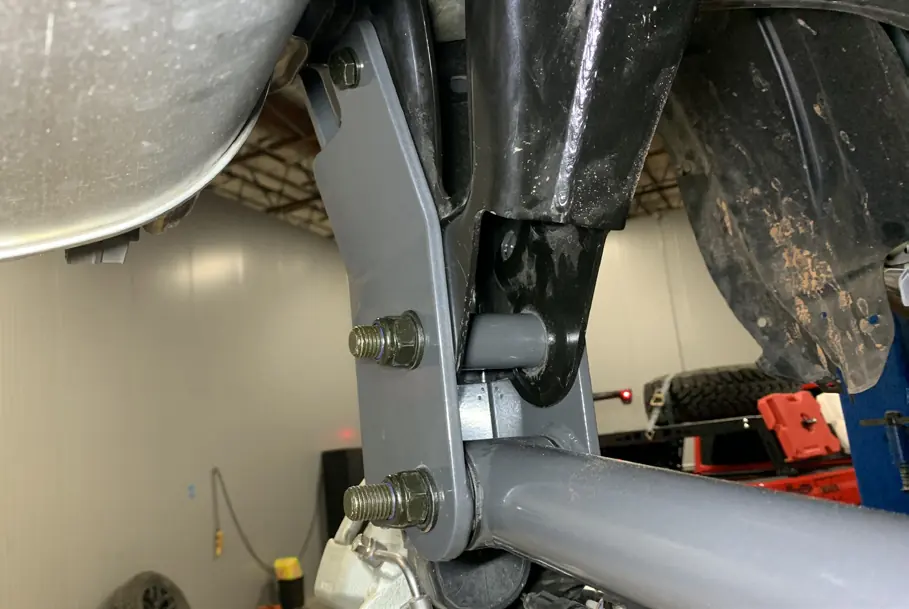
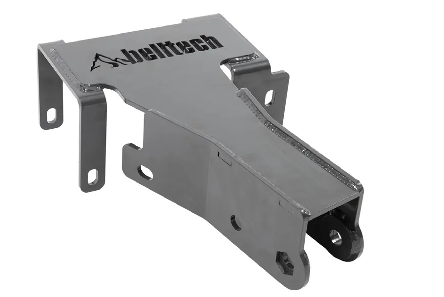
- Mount the Belltech rear roll center correction bracket.
- Install the M16 bolt through the bracket and frame, ensuring correct orientation.
- Install inner frame support plates.
- Install the Belltech track bar.
- Install the Belltech brake line extension bracket.
- Replace factory control arms with new Belltech adjustable control arms.
- Raise the axle to ride height before torquing control arm bolts to 159 ft lbs.
- Raise the fuel tank back into position and reconnect all lines.
- Check clearance between the passenger upper control arm bolt cover and the fuel tank skid plate.
Finalizing the Installation
Re-install the wheels, lower the vehicle, and torque the lug nuts to 100 ft lbs. Perform a final check of all fasteners and components. A professional alignment is required immediately following installation.
Practical help
Common problems
Fuel tank interference
The fuel tank must be lowered to access passenger control arm bolts; it is suggested to have a low fuel level before starting.
Alignment issues
Professional alignment is required immediately after installation to ensure safe operation.
Clearance concerns
Ensure a minimum of 5mm clearance between the differential and the frame/steering rack after installation.
Before use
- Verify all components against the parts list.
- Measure hub to fender heights before starting.
- Ensure vehicle is on a level, concrete or seasoned asphalt surface.
- Use proper support stands; never work under a vehicle supported only by a jack.
- Check brake hoses and cables for interference.
- Ensure the transmission is in PARK (automatic) or 1st gear (manual).
Specs in practice
- Lower ball joint nut
- Torque to 85 ft lbs.
- Upper ball joint nut
- Torque to 46 ft lbs.
- Control arm bolts
- Torque to 159 ft lbs.
Images and diagrams
- Figure 1 & 2: Shows the specific cut lines required on the rear cross member.
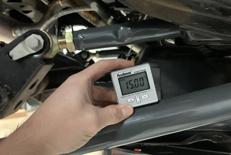
- Control Arm Angles: Shows how to use an angle gauge to set rear control arms to 9 degrees (upper) and 15 degrees (lower) for proper alignment.
Model compatibility
- Fits Ford Bronco 4WD 2021+.
- Ride height for 152600HK is 4 to 7.5 inches.

Manual page author
Michael Turner
Technical manual editor
Reviews PDF manuals for structure, safety notes, and practical product details so readers can find the right information quickly.