Automotive / Suspension Kits
Installation Instructions for Belltech 150201HK Suspension Lift Kit
Comprehensive installation guide for the Belltech 150201HK 7-inch suspension lift kit for 07-15 GM 1500 vehicles. Includes step-by-step removal and installation procedures for front and rear components, parts list, and safety warnings.
Table of contents
Manual images
Click an image to enlargeImportant Information
This document provides installation instructions for the Belltech 150201HK 7-inch lift kit designed for 07-15 GM 1500 vehicles. Before beginning, ensure all hardware listed in the parts list is present. Do not work under a vehicle supported only by a jack; use properly rated support stands. Always torque hardware to specified values and check for wheel/tire interference before driving.
Compatibility and Preparation
Before installation, verify you have the correct kit for your vehicle's specific upper control arm type. Using the wrong kit will result in poor fit and failure of parts. The kit is compatible with vehicles equipped with Aluminum, Stamped Steel, or Cast Steel upper control arms. Measure hub-to-fender heights before starting to compare with the final result.
Parts List Overview
The kit includes various components such as front and rear crossmembers, lift spindles, CV axle spacers, compression arms, skid plates, rear lift blocks, and necessary hardware kits (labeled A-H). Refer to the detailed parts list in the manual to verify all components before starting.
Front Removal Instructions
1. Park on a level surface, engage the parking brake, and chock the rear wheels. Support the vehicle on jack stands.
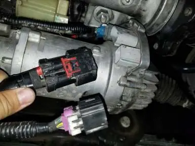
2. Remove wheels, sway bar, tie-rod ends, brake lines, and ABS sensor wires.
3. Remove brake calipers and rotors.
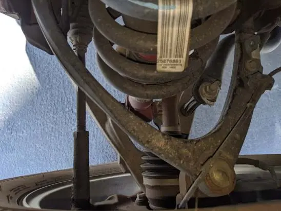
4. Remove the axle nut, then separate the upper and lower ball joints from the spindle.
5. Remove the strut assembly and CV axle.
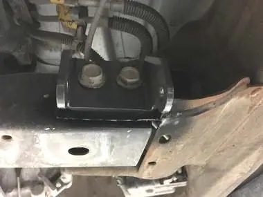
6. Remove the lower control arms, OEM gravel guards, and the crossmember underneath the differential.
7. Trim the crossmember area as marked in the instructions (required for rear driver's side mount) and smooth any sharp edges.
Front Installation Instructions
1. Install the new front and rear crossmembers and torque to 130 ft-lb.
2. Install lower control arms and support rods.
3. Install CV axles with spacers, new sway bar, and strut assembly.
4. Install the lift spindle, tie rod ends, and brake brackets.
5. Reinstall ABS harness, rotors, and calipers.
6. Install the skid plate and compression arms. Torque compression arm bolts to 100 ft-lb.
Rear Removal and Installation
1. Support the rear axle and remove factory shock absorbers, u-bolts, and lift blocks.
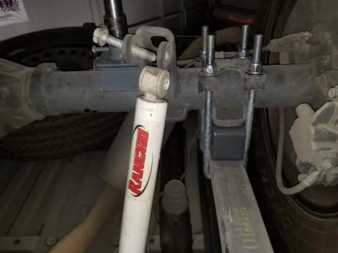
2. Install the new lift block on the factory spring pad with the tapered end facing the front.
3. Install new u-bolts and tighten in a crossing pattern.
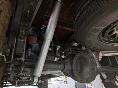
4. Install new shock absorbers using factory hardware.
5. Reattach brake lines and ensure there is sufficient slack.
Post-Installation Checks
After installation, verify all components are properly torqued. Check brake hoses for interference. Test drive the vehicle in a remote location to adjust to the altered handling. It is highly recommended to have the vehicle professionally aligned to factory specifications. Re-torque all hardware after 10, 100, and 1000 miles.
Practical help
Common problems
Interference with wheel assembly
Check wheel assembly to spindle, suspension component, and fender/body clearance before tightening lug nuts and rotating.
Differential interference
Trim the crossmember area as marked in the instructions (only for rear driver's side mount).
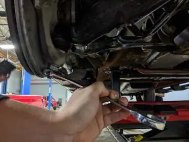
Ball joint spinning during removal
Use a 10mm wrench to hold the stud while loosening the nut.
Before use
- Verify all parts from the list are present
- Measure hub-to-fender height
- Park on level surface and engage parking brake
- Use wheel chocks
- Ensure vehicle is properly supported on jack stands
Specs in practice
- Crossmember torque
- 130 ft-lb
- Axle nut torque
- 180 ft-lb
- Ball joint torque
- 85 ft-lb
- Sway bar end link torque
- 35 ft-lb
- Skid plate torque
- 50 ft-lb (front), 30 ft-lb (rear)
Images and diagrams
- Photos 1-4: Front removal steps
- Photos 14-16: Crossmember trimming guide
- Photos 17-28: Front installation steps
- Photos 29-32: Rear installation steps
Model compatibility
- Compatible with 07-15 GM 1500 models
- Requires specific kit based on control arm type (Aluminum, Stamped Steel, or Cast Steel)

Manual page author
Michael Turner
Technical manual editor
Reviews PDF manuals for structure, safety notes, and practical product details so readers can find the right information quickly.