Automotive / Suspension Kits
Installation Guide for BDS 1740FPE 2 Inch Lift Kit
Comprehensive installation guide for the BDS 1740FPE 2 Inch Lift Kit. Includes step-by-step instructions, safety warnings, tire fitment specifications, and pre-installation measurement procedures for Dodge/Ram 1500 4WD vehicles.
Quick answers from the manual
Quick answer
- This guide provides installation instructions for the BDS 1740FPE 2 Inch Lift Kit for Dodge/Ram 1500 4WD vehicles. It covers safety, pre-installation measurements, component assembly, and troubleshooting. p. 1, 5, 8
Key actions
- Measure ride height before installation p. 4
- Install upper control arms p. 8
Problems and fixes
Driveline vibration
Lower ride height to reduce CV angles or seek separate manufacturer drop kits/CV conversion.
p. 5Maintenance and reset
- Grease the ball joint at regular service intervals. p. 8
- Recheck hardware after 500 miles. p. 8
Technical specifications
| Parameter | Value | Meaning | Pages |
|---|---|---|---|
| Shock top hat bolts torque | 24 ft-lbs | Tightening torque for shock top hat bolts | p. 7 |
| Upper control arm bushing hardware torque | 130 ft-lbs | Tightening torque for control arm bushing hardware | p. 8 |
Where to find it in the PDF
- Kit Contents p. 3
- Pre-Installation Measurements p. 4
- Installation Instructions p. 5, 6, 7, 8
Table of contents
Manual images
Click an image to enlargeQuick guide from the manual
This document provides installation instructions for the BDS 1740FPE 2 Inch Lift Kit designed for Dodge/Ram 1500 4WD vehicles (2006-2024). Professional installation is recommended. Before beginning, ensure you have the necessary tools, including a torque wrench and the 8677 Chrysler Ball Joint Separation Tool. Always measure ride height before and after installation to ensure proper setup.
Safety and Preparation
Prior to installation, read all instructions and warnings. Ensure the vehicle is parked on a clean, flat, and level surface. Block the rear wheels for safety. Support the frame rails with jackstands when the front of the vehicle is raised. Always wear safety glasses when using power tools.
Tires and Wheels Fitment
For 2006-2018 Models: Works with stock rims with stock tires, or up to 12.50" wide tires on 17/18/20x9 wheels with 4.5"-5" backspacing.
For 2019+ Models: Works with stock rims with stock tires, or up to 12.50" wide tires on 18/20x9 wheels with 4.5"-5" backspacing.
Pre-Installation Measurements
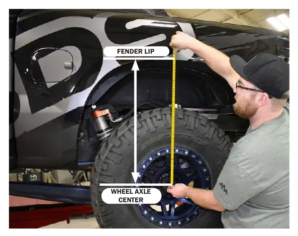
It is required to take ride height measurements before and after installation. Measure from the WHEEL AXLE CENTER up to the FENDER LIP of the wheel opening for all 4 wheels. Record these measurements as they may be required for technical support.
Installation Overview
The installation process involves the following key phases:
- Front Disassembly: Park on a level surface, block rear wheels, raise the front, and support with jackstands. Remove front wheels, disconnect ABS wires, and remove the upper control arm.
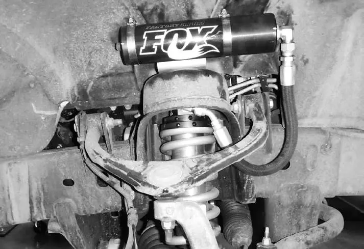
- Coilover Installation: Install the new coilover assembly. For remote reservoir models, ensure hoses face outward and toward the front of the vehicle. Tighten top hat bolts to 24 ft-lbs.
- Control Arm Installation: Install the new arm with factory hardware. Torque specifications vary by model year (52 ft-lbs for 2006-2011; 26 ft-lbs plus 180 degrees for 2012+).
Troubleshooting and Maintenance
If you experience driveline vibration, the ride height may need to be lowered to reduce CV angles. Note that this kit will not work with stock rims and 12.50" wide tires at full steering lock. Grease the ball joint at regular service intervals and recheck all hardware after 500 miles.
Practical help
Common problems
Driveline vibration
If vibration occurs, lower the ride height to reduce CV angles or seek separate manufacturer drop kits/CV conversion.
Tire rubbing
The kit will not work with stock rims and 12.50" wide tires at full steering lock.
Before use
- Measure ride height from wheel axle center to fender lip before and after installation
- Ensure vehicle is on a clean, flat, and level surface
- Block rear wheels for safety
- Support frame rails with jackstands
- Verify tire and wheel clearance
- Perform a head light check and adjustment after installation
Specs in practice
- Upper ball joint nut (2006-2011)
- Torque to 52 ft-lbs
- Upper ball joint nut (2012+)
- Torque to 26 ft-lbs plus 180 degrees
- Shock top hat bolts
- Torque to 24 ft-lbs
- Upper control arm bushing hardware
- Torque to 130 ft-lbs
Images and diagrams
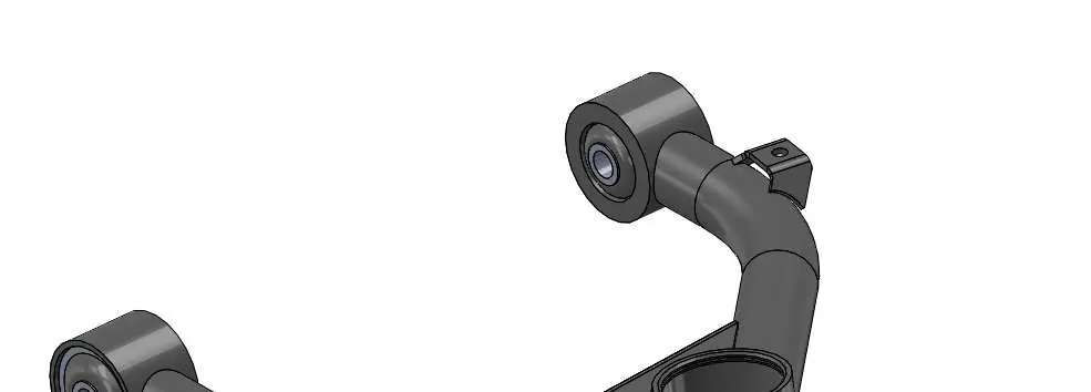
- The kit contents diagram identifies the driver and passenger side control arms, ball joints, and hardware.
- The pre-installation diagram illustrates the correct measurement points from the wheel axle center to the fender lip.
- The coilover installation diagram shows the orientation of the remote reservoir and hose routing.
Model compatibility
- BDS122252 only works with BDS 4" or 6" strut spacer lift systems or BDS 6" Fox Coilover lift systems.
- BDS122253 only works with BDS 2-3" spacer lift systems or 2-3" Fox Coilover lift systems.

Manual page author
David Miller
Documentation analyst
Organizes user manual content into clear summaries, with attention to model details, product context, and everyday usability.