HVAC / Water Heaters
High Temperature Kit Installation Manual for Bradford White RTG 199HE / RTG 199ME
Installation and configuration guide for the High Temperature Kit for Bradford White RTG 199HE and RTG 199ME water heaters. Includes step-by-step instructions for jumper installation, software configuration, and safety precautions.
Quick answers from the manual
Quick answer
- The High Temperature Kit allows the water heater to reach temperatures up to 184 °F (84 °C). Installation requires opening the control unit, installing specific jumpers (JP7/JP8 for ME models, JP2/JP5 for HE models), and performing software configuration for HE models. p. 3, 4, 5
Key actions
- Power off and unplug the unit before servicing. p. 3
- Access the PCB by removing the control unit front screws and rear hatch. p. 3
Technical specifications
| Parameter | Value | Meaning | Pages |
|---|---|---|---|
| RTG 199ME High Temp Range | 38 °C - 84 °C (100 °F - 184 °F) | Temperature range with JP7+JP8 installed | p. 4 |
| RTG 199HE High Temp Range | 38 °C - 84 °C (100 °F - 184 °F) | Temperature range after software configuration | p. 5 |
Where to find it in the PDF
- Introduction and Preparation p. 3
- RTG 199ME Instructions p. 4
- RTG 199HE Instructions p. 5
Table of contents
Manual images
Click an image to enlargeQuick guide from the manual
This document provides instructions for installing the High Temperature Kit on Bradford White RTG 199HE and RTG 199ME water heaters. The installation involves accessing the control unit, installing specific jumpers, and configuring the software settings. Note: Installing this kit reduces the heat exchanger warranty to 5 years from the date of original installation.
Tools needed:
- Phillips head screwdriver
- Small flat head screwdriver
- Needle-nosed pliers
Preparation
Before starting, ensure the water heater is powered off and disconnected from the power supply to prevent electric shock. Loosen the two Phillips head screws on the bottom rear of the front cover, pull the cover bottom outwards, and lift it upwards to remove.
Control unit service position
To access the circuit board:
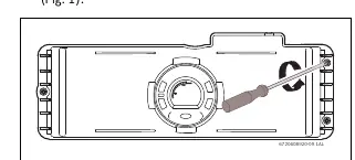
- Remove the three Phillips screws on the front of the control unit.
- Turn the control unit to expose the rear.
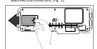
- Remove the rear hatch from the control unit to expose the circuit board electrical connections.
Notice: Avoid touching the printed circuit board (PCB) as static discharge may damage the circuitry.
RTG 199ME Models
For RTG 199ME models, follow these steps:
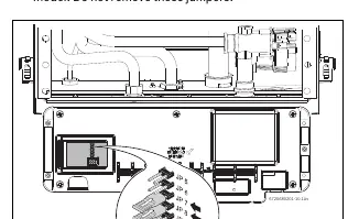
- Do not remove existing jumpers 5 and 6.
- Install the jumpers from the kit on positions JP7 and JP8.
- Reinstall the rear hatch and control unit.
- Power on the appliance. Press the + button to reach temperatures above 140 °F (60 °C).
RTG 199HE Models
For RTG 199HE models, follow these steps:
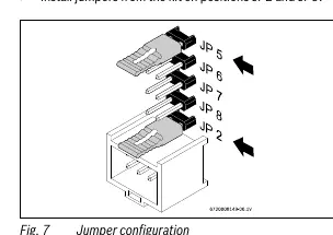
- Install the jumpers from the kit on positions JP2 and JP5.
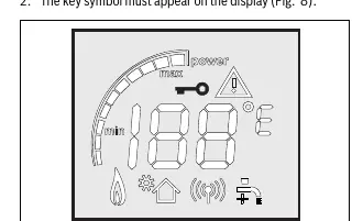
- Power on the appliance. The key symbol must appear on the display.
- Press and hold the + or - and P buttons simultaneously for 3 seconds until the display reads P2.
- Use the + or - button to cycle through programs until the display shows PE.
- Press P to enter PE adjustment.
- Use the + or - button to select C.
- Hold the P button for 5 seconds until the display flashes C.
- Turn off the appliance, remove the jumpers from the PCB, and store them with the technical documentation.
- Reinstall the rear hatch and control unit.
- Power on the appliance and press the + button to reach temperatures above 140 °F (60 °C).
Important Safety and Warranty Information
Always unplug the power supply cord before servicing to avoid fatal injury from electric shock. For DHW recirculating applications, contact a qualified technician to avoid damage to internal components.
Practical help
Common problems
Static discharge damage to PCB
Avoid touching the printed circuit board directly.
Electric shock risk
Always unplug the power supply cord before servicing.
DHW recirculating application damage
Contact a qualified technician for installation in these applications.
Before use
- Ensure power button is set to OFF
- Unplug power cord from outlet
- Prepare Phillips screwdriver, small flat head screwdriver, and needle-nosed pliers
- Identify if your model is RTG 199ME or RTG 199HE
Specs in practice
- RTG 199ME Temperature Range (Standard)
- 38 °C - 60 °C (100 °F - 140 °F)
- RTG 199ME Temperature Range (High)
- 38 °C - 84 °C (100 °F - 184 °F) with JP7+JP8 installed
- RTG 199HE Temperature Range (Standard)
- 38 °C - 60 °C (100 °F - 140 °F)
- RTG 199HE Temperature Range (High)
- 38 °C - 84 °C (100 °F - 184 °F) after software configuration
Images and diagrams
- Fig 1: Shows the location of the three Phillips screws on the front of the control unit.
- Fig 2: Shows how to remove the rear hatch to access the PCB.
- Fig 4: Shows jumper positions JP7 and JP8 for RTG 199ME.
- Fig 7: Shows jumper positions JP2 and JP5 for RTG 199HE.
Model compatibility
- Kit is specifically for RTG 199HE and RTG 199ME models.
- Installation reduces heat exchanger warranty to 5 years.

Manual page author
David Miller
Documentation analyst
Organizes user manual content into clear summaries, with attention to model details, product context, and everyday usability.