HVAC / Water Heaters
Installation Manual for Bradford White RTG 199HE Cascade Venting System
Comprehensive installation guide for the Bradford White RTG 199HE Cascade Venting System. Includes safety warnings, assembly steps, venting requirements, and installation diagrams.
Quick answers from the manual
Quick answer
- This manual provides installation instructions for the back-to-back cascade venting system for the Bradford White RTG 199HE water heater, including safety guidelines, assembly steps, and venting length limitations. p. 1, 3, 14
Key actions
- Ensure installation is performed by a licensed contractor. p. 3
- Lubricate all gaskets before assembly. p. 7
Problems and fixes
Smell of flue gas
Switch off the appliance, open windows and doors, and contact a certified installer.
p. 3Technical specifications
| Parameter | Value | Meaning | Pages |
|---|---|---|---|
| Max Vent Length | 100 ft (30m) | Total combined horizontal and vertical length. | p. 14 |
| Min Horizontal Run | 40 in (1m) | Minimum horizontal run required. | p. 14 |
Where to find it in the PDF
- Safety Instructions p. 3, 4
- Accessory Assembly p. 5, 6, 7, 8
- Vent Lengths p. 14
Table of contents
Manual images
Click an image to enlargeQuick guide from the manual
This document provides installation instructions for the back-to-back cascade venting system designed for the Bradford White RTG 199HE water heater. It covers safety requirements, component assembly, and venting specifications. Installation must be performed by a licensed contractor.
Safety instructions
Failure to follow these instructions can result in severe personal injury, death, or property damage. Key safety points include:
- Flue gas: If you smell flue gas, switch off the appliance, open windows and doors, and contact a certified installer.
- Ventilation: Never close off or reduce the size of air intake and outlet openings. Ensure vent pipes and chimneys are not damaged or blocked.
- Combustion air: Keep combustion air free of corrosive substances like halogenated hydrocarbons.
- Installation: Only use materials with adequate temperature stability. In Massachusetts, installation must be performed by a licensed plumber.
Combustion air requirements
The system requires specific air volume for operation:
- Each appliance requires 9,950 cubic feet of available combustion air or a minimum of 1.243 square feet of space with an 8-foot ceiling.
- If the space is confined, two permanent openings are required (one within 12 inches of the top, one within 12 inches of the bottom).
- Refer to the National Fuel Gas Code for specific sizing based on BTU/Hr requirements.
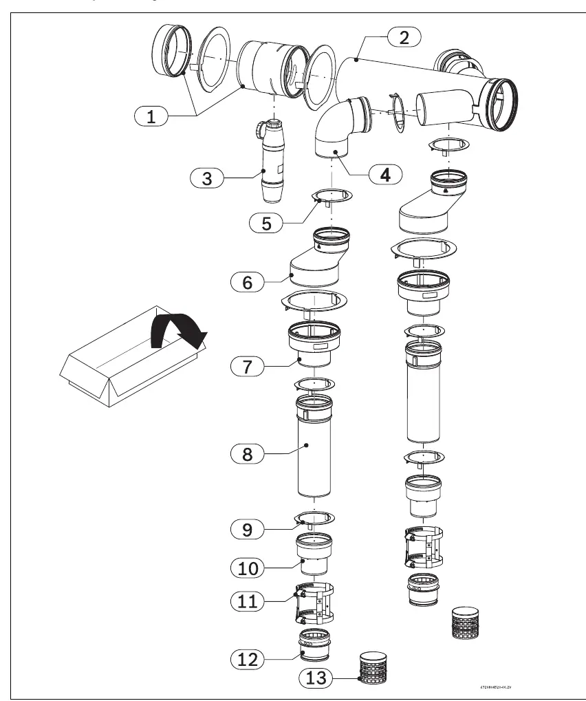
Accessory assembling
The system consists of various components including header pipes, condensate traps, reducers, and elbows. Ensure all gaskets are lubricated evenly before assembly. Follow the provided diagrams for the correct sequence of parts.
Installation steps
The installation involves mounting the system to the wall and connecting the venting components:
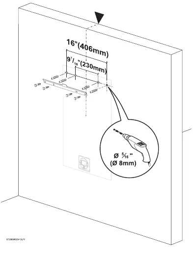

- Drill holes according to the specified dimensions (16" x 9 1/16").
- Mount the support brackets.
- Assemble the venting components as shown in the diagrams, ensuring all connections are sealed gas-tight.
- For vertical setups, use the appropriate termination kits and extensions.
- Consult a professional roofer for roof flashing to ensure a water-tight seal.
Vent lengths
Adhere to the following limits for the venting system:
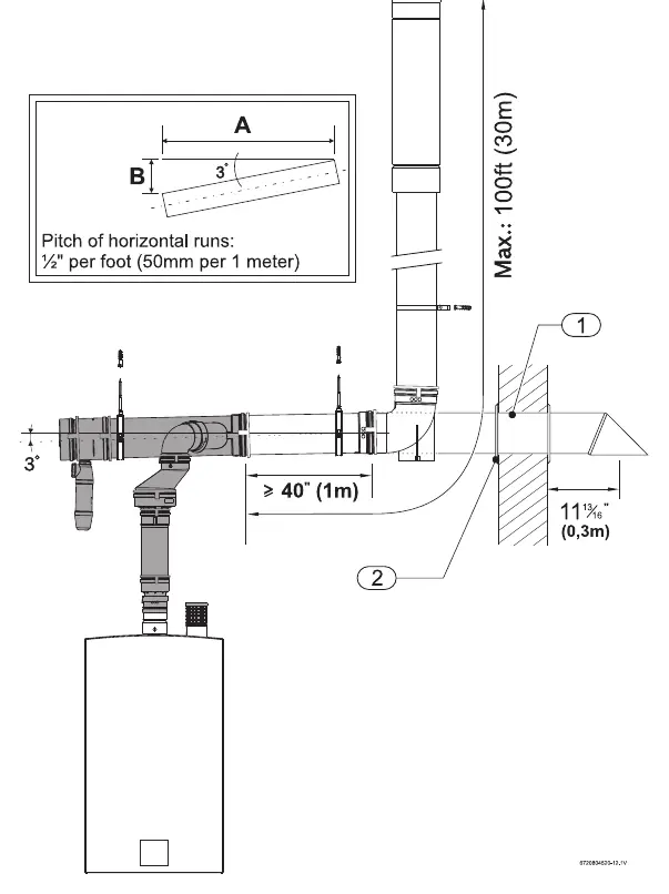
- Minimum vent length: A minimum of 40 inches (1m) of horizontal run is required (excluding headers and termination).
- Maximum vent length: The total combined horizontal and vertical vent length must not exceed 100 feet (30m).
Practical help
Common problems
Smell of flue gas
Switch off the appliance immediately, open windows and doors, and inform a trained and certified installer.
Insufficient ventilation
Ensure air intake and outlet openings are not blocked or reduced in size. Do not operate until obstructions are removed.
Before use
- Ensure installation is performed by a licensed contractor.
- Verify that all vent pipes and chimneys are free of damage and blockages.
- Confirm the installation site provides sufficient combustion air.
- Check that all vent joints are sealed gas-tight.
- Consult a professional roofer for roof flashing installation.
Specs in practice
- Maximum vent length
- 100 feet (30m) total combined horizontal and vertical length.
- Minimum horizontal run
- 40 inches (1m) required.
- Combustion air requirement
- 9,950 cubic feet of available air per appliance.
Images and diagrams
- Fig 1: Exploded view of the accessory components and parts list.
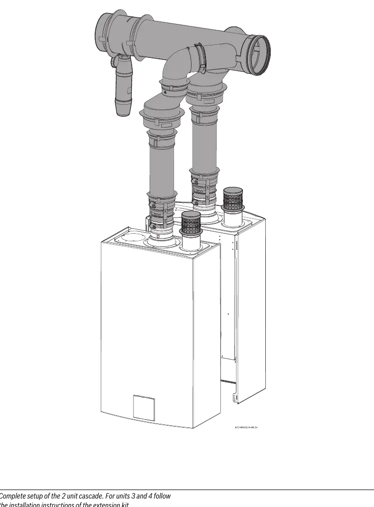
- Fig 15: Complete setup of the 2-unit cascade system.
- Fig 25: Diagram showing maximum and minimum vent length requirements.
Model compatibility
- Approved for use with RTG 199HE and RTG 199ME models.
- Approved for use in the US and Canada.
- In Canada, use only ULCS636 approved vent material.

Manual page author
Michael Turner
Technical manual editor
Reviews PDF manuals for structure, safety notes, and practical product details so readers can find the right information quickly.