Lighting / Ceiling Fans
Breezary 36-inch Ceiling Fan User Guide
Comprehensive user guide for the Breezary 36-inch ceiling fan (Model 24004-BK). Includes detailed installation instructions, wiring diagrams, remote control setup, and troubleshooting tips for balancing and operation.
Quick answers from the manual
Quick answer
- The Breezary 36-inch ceiling fan (24004-BK) requires a metal outlet box capable of supporting 50 lbs. Installation involves mounting the hanger bracket, assembling the downrod, and connecting wires according to the provided diagram. The remote control uses a 12V battery and requires matching code settings between the transmitter and receiver. p. 1, 4, 6
Key actions
- Install hanger bracket p. 4
- Connect wiring p. 5
- Set remote codes p. 6
First start
- Install 12V battery in remote p. 7
- Ensure blade clearance p. 5
Show 4 more answers Show less
Problems and fixes
Fan wobbles
Check blade mounting screws, measure blade level, check for warped blades.
p. 8Maintenance and reset
- Periodic cleaning p. 8
Technical specifications
| Parameter | Value | Meaning | Pages |
|---|---|---|---|
| Voltage | 110-120V | Operating voltage | p. 6 |
| Max Amps | 1.0A | Maximum fan motor amps | p. 6 |
| Max Light Watts | 180W | Maximum light wattage | p. 6 |
Where to find it in the PDF
- Safety Instructions p. 2
- Parts List p. 3
- Installation p. 4, 5
- Remote Control p. 6, 7
- Maintenance p. 8
Table of contents
Manual images
Click an image to enlargeQuick Guide from the Manual
This guide covers the installation and operation of the Breezary 36-inch ceiling fan. Before beginning, ensure your ceiling outlet box is metal and capable of supporting at least 50 lbs. The fan requires a minimum clearance of 7 feet (230 cm) from the floor to the blades. Do not use this fan with solid-state wall controls.
Installation
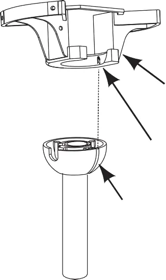
Hanger Bracket: Securely attach the hanger bracket to the ceiling joist using the provided lag bolt, flat washers, and lock washer.
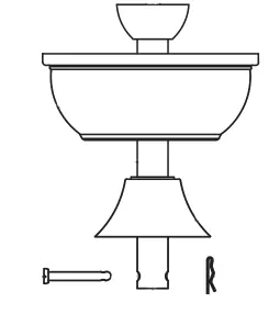
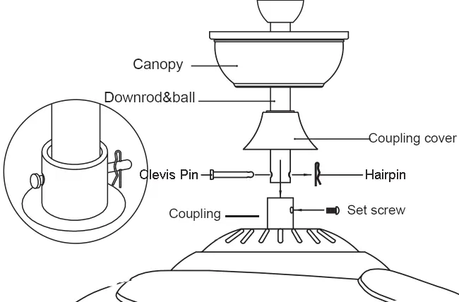
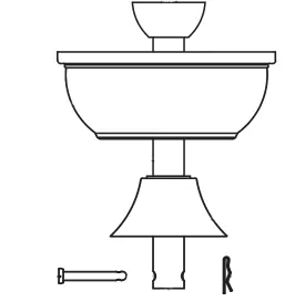
Downrod Assembly: Remove the clevis pin and hairpin from the downrod. Pass the downrod through the canopy and coupling cover. Insert the downrod into the downrod support, align the holes, and secure with the clevis pin and hairpin. Tighten the set screws.
Wiring: Connect the wires according to the diagram:
- Green wire: Connect to the Bare/Green (ground) supply wire.
- Blue wire: Connect to the blue fan wire.
- Black wire: Connect to the black fan wire.
- White wire: Connect to the white fan wire.
- Red wire: Connect to the Black (live) supply wire.
- White wire (second): Connect to the White (neutral) supply wire.
Remote Control
The remote control system uses 16 code combinations. To set the codes, remove the battery cover on the transmitter and adjust the code switches. Ensure the switches on the receiver (located in the ceiling canopy) match the settings on the transmitter. The remote requires a 12V battery (not included).
Maintenance and Troubleshooting
Cleaning: Periodically clean the fan using a soft, lint-free brush or cloth. Do not use solvents, as they may damage the engine or cause electrical shocks.
Balancing: If the fan wobbles, check that all blade mounting screws are tight. Measure the distance from each blade tip to the ceiling to ensure the blades are level. If a blade is out of shape, it may need to be removed and checked on a flat surface.
Practical help
Common problems
Fan wobbles during operation
Check that all blade mounting screws are tight. Measure the distance from each blade tip to the ceiling to check for levelness. If inconsistent, check for warped blades.
Remote control not operating the fan
Check the 12V battery. Ensure the code switches on the transmitter match the code switches on the receiver.
Fan does not start
Check wiring connections, ensure the circuit breaker is on, and verify the remote battery is installed correctly.
Before use
- Ensure the ceiling outlet box is metal and supports 50 lbs
- Verify 7 feet (230 cm) clearance from floor to blades
- Check all wiring connections against the diagram
- Install a 12V battery in the remote transmitter
- Ensure code switches on transmitter and receiver match
Show more Show less
Images and diagrams
- Figure 1: Hanger bracket installation to ceiling joist
- Figure 3: Downrod and canopy assembly
- Figure 6b: Wiring diagram for receiver and power supply
Model compatibility
- Do not use with solid-state wall controls
- Not suitable for sloped ceilings
- Requires 12V battery (not included)

Manual page author
David Miller
Documentation analyst