Hvac / Thermostats Controls
Installation Guide for Danfoss Aero RA click Thermostatic Sensor
Quick installation and configuration guide for the Danfoss Aero RA click thermostatic sensor, including mounting, temperature limitation, and theft protection steps.
Table of contents
Manual images
Jump to the sectionQuick guide from the manual
This document provides essential instructions for the installation, temperature limitation, and security setup of the Danfoss Aero RA click thermostatic sensor. It covers standard installation, BIV installation, uninstallation, and how to restrict temperature ranges or enable theft protection.
Installation
The sensor features a click-on mechanism for easy mounting:

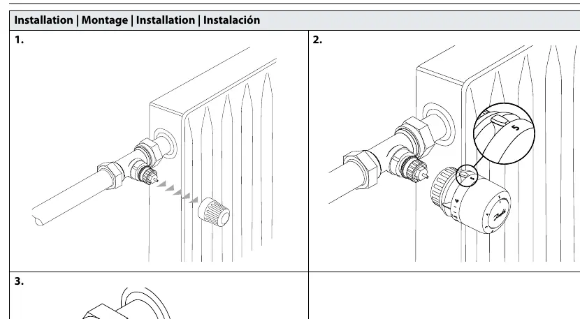
- Ensure the sensor is set to the maximum position.
- Align the sensor with the valve body.
- Press the sensor firmly onto the valve until you hear a distinct click, indicating it is securely locked in place.
BIV Installation
For BIV (Built-in Valve) configurations, follow the same click-on procedure: remove the protective cap, align the sensor, and press until it clicks onto the valve interface.
Uninstallation
To remove the sensor, firmly grip the base and pull it away from the valve body while ensuring the locking mechanism is released.
Temperature Limitation
You can restrict the temperature range to prevent overheating or overcooling:
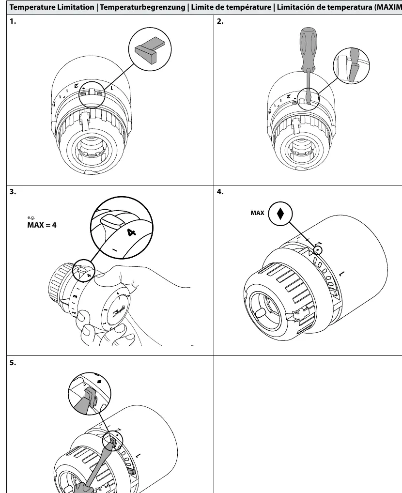
- Maximum Limitation: Use the provided limiter tool to set a maximum temperature stop. Insert the tool into the slot, adjust to the desired maximum value (e.g., 4), and secure it.
- Minimum Limitation: Similarly, use the limiter tool to set a minimum temperature stop by inserting it into the corresponding slot and adjusting to the desired minimum value (e.g., 2).
Theft Protection
To prevent unauthorized removal of the sensor:
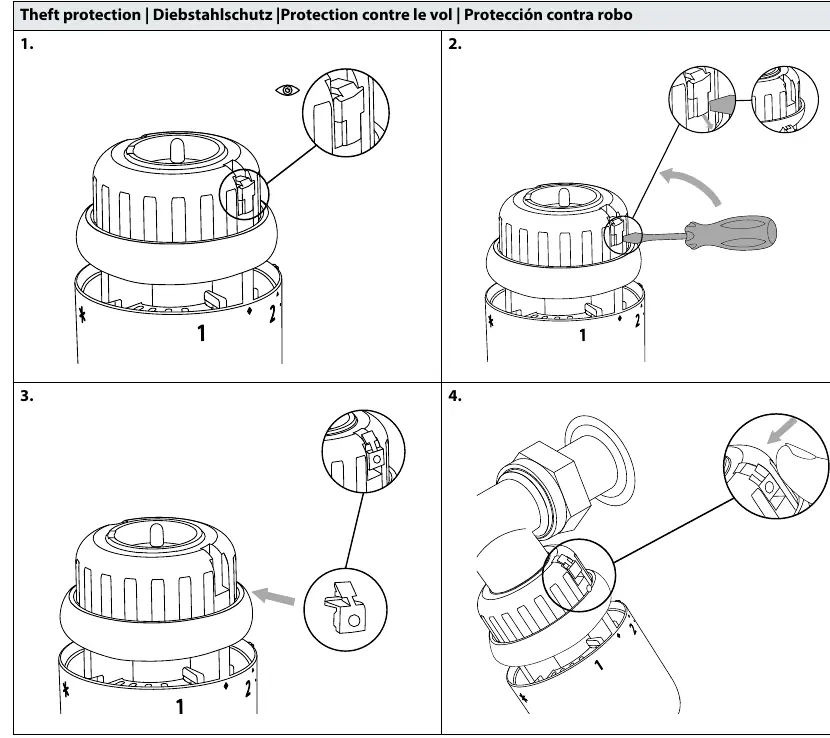
- Locate the theft protection slot on the side of the sensor.
- Insert the security clip or screw mechanism as shown in the diagrams to lock the sensor onto the valve.
- To remove the sensor later, use a screwdriver to disengage the security lock before pulling the sensor off.
Manufacturer information
Danfoss A/S
Practical help
Common problems
Sensor does not click onto the valve
Ensure the sensor is set to the maximum position before attempting to mount it.
Need to remove a theft-protected sensor
Use a screwdriver to disengage the security lock mechanism before attempting to pull the sensor off the valve.
Before use
- Verify the valve body is compatible with the RA click system.
- Ensure the sensor is set to the maximum position before installation.
- Have the temperature limiter tool ready if you intend to set specific temperature ranges.
- Check if theft protection is required for your installation environment.
Images and diagrams
- The 'click' sound confirms the sensor is correctly locked onto the valve.
- The diamond symbol indicates the maximum temperature setting point.
- The triangle symbol indicates the minimum temperature setting point.
- The blind mark on the sensor housing helps with alignment during installation.
Model compatibility
- Designed for use with Danfoss RA click compatible valve bodies.

Manual page author
David Miller
Documentation analyst
Organizes user manual content into clear summaries, with attention to model details, product context, and everyday usability.