Automotive / Lighting Accessories
Cell2 KUIPER-FIT Illuminated Centre Lightbar LKPR-F Operation Manual
Quick guide for the Cell2 KUIPER-FIT Illuminated Centre Lightbar (LKPR-F). Includes wiring diagrams, flash pattern selection, and installation instructions.
Table of contents
Manual images
Click an image to enlargeQuick Guide
This manual provides essential installation and operation instructions for the Cell2 KUIPER-FIT lightbar. Proper installation requires a solid understanding of automotive electronics. It is highly recommended to configure and test all functions before final installation.
Wiring and Installation
The lightbar requires connection to the vehicle's electrical system. All function wires (inputs) are activated by applying +VDC continuously.
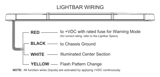
- Black Wire: Connect to the vehicle chassis ground.
- Red Wire: Connect to a fused switch for Warning Mode.
- White Wire: Connect to a fused switch for the Illuminated Center Section.
- Yellow Wire: Used for Flash Pattern Change.
After mounting the lightbar, route the control cable into the vehicle to the switch panel or controller location. Connect the Red and White wires to a fused switch for independent control.
Functions and Operation
Warning Mode (Red Wire): Activate by applying +VDC to the Red wire.
Flash Pattern Change (Yellow Wire): While in Warning Mode, tap +VDC to the Yellow wire to change patterns:
- Quick tap (once): Advances to the next flash pattern.
- Quick tap (3 times): Resets to FP#1 (default Flash Pattern).
Illuminated Center Section (White Wire): Activate by applying +VDC to the White wire. Note: This wire will not activate any function if the lightbar was ordered without ICS lights.
Flash Patterns
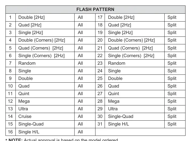
The lightbar supports 31 different flash patterns, categorized into 'All' (full bar) and 'Split' (split bar) modes. Patterns include Double, Quad, Single, Random, Quint, Mega, Ultra, Cruise, and Single H/L.
Warnings and Maintenance
- Faulty connections may cause the lightbar to malfunction or reset to default settings.
- Do not use a high-pressure power washer to clean the lightbar, as this may damage the unit and void the warranty.
Manufacturer information
Cell2
Practical help
Common problems
Lightbar malfunctions or resets to default settings
Check all wiring connections for faults or loose contacts.
Illuminated Center Section (ICS) does not activate
Ensure the lightbar was ordered with the ICS option; the White wire will not function if the unit was not configured with ICS lights.
Before use
- Verify the vehicle's electrical system voltage.
- Determine and configure required functions prior to installation.
- Ensure all wires are connected to a fused switch for safety.
- Test all flash patterns and functions before final mounting.
Images and diagrams
- The wiring diagram illustrates the four input wires (Red, Black, White, Yellow) and their respective functions for power, ground, and control.
Model compatibility
- All function wires are activated by applying +VDC continuously.

Manual page author
Emily Carter
User documentation editor
Prepares concise manual descriptions and highlights the most useful setup, operation, and maintenance information for readers.