Automotive / Lighting Accessories
Operation Manual for Cell2 Kuiper HE Illuminated Centre Lightbar
Quick guide for the Cell2 Kuiper HE Illuminated Centre Lightbar. Includes wiring diagrams, function setup, flash pattern programming, and installation instructions.
Table of contents
Manual images
Click an image to enlargeQuick Guide
The Cell2 Kuiper HE Illuminated Centre Lightbar requires proper automotive electrical knowledge for installation. Always test functions before final installation. Ensure all power connections are secure and fused to prevent damage.
Wiring Instructions
Follow these steps to connect the lightbar:
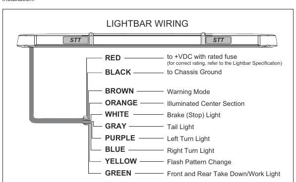
- Red Wire: Connect to +VDC with a user-supplied fuse. Refer to the lightbar specification for the correct fuse rating.
- Black Wire: Connect to the vehicle chassis ground.
- Control Wires: Route these wires to a user-supplied switch panel in the dash area.
When routing wires through the firewall, use existing factory harness paths or drill a new hole, ensuring no components are damaged during the process.
Functions and Operation
The lightbar features several control wires for different functions:
- Brown Wire: Activates Warning Mode.
- Orange Wire: Activates the Illuminated Center Section (ICS).
- Green Wire: Activates Front and Rear Take Down/Work Light.
- Yellow Wire: Used for Flash Pattern Change and Dim Mode.
Flash Pattern Programming
The Yellow wire has three functions depending on how it is used:
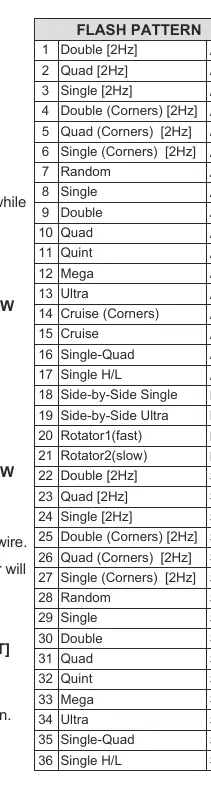
- Flash Pattern Change only: Tap +VDC to the Yellow wire while in warning mode. Quick tap once for the next pattern; quick tap 3 times to reset to default.
- Dim Mode only: Apply +VDC to the Yellow wire while in warning mode to activate low power.
- Flash Pattern Change & Dim Mode: Tap +VDC (<1 second) to change patterns. Apply +VDC (>1 second) to activate low power.
To program the Yellow wire function:
- Activate warning mode (Brown wire).
- Quickly tap +VDC to the Green wire 3 times to enter programming mode.
- The front lightheads will flash to indicate the current function: Single flash (Pattern Change only), Double flash (Dim Mode only), or Triple flash (Pattern Change & Dim Mode).
- Tap +VDC to the Yellow wire to cycle through functions.
- Disconnect power to save and exit.
Brake, Tail, and Turn Indicators
The lightbar includes auxiliary lighting functions:
- White Wire: Brake (Stop) Light.
- Gray Wire: Tail Light.
- Purple Wire: Left Turn Signal.
- Blue Wire: Right Turn Signal.
Caution: These lights are auxiliary and must not replace the original vehicle lamps.
Important Warnings
- Do not use the power wire as the activation switch.
- Do not use a high-pressure power washer to clean the lightbar, as this may damage the unit and void the warranty.
- Faulty connections may cause the lightbar to malfunction or reset to default settings.
Manufacturer information
Cell2
Practical help
Common problems
Lightbar malfunctions or resets to default settings
Check for faulty wiring connections and ensure all wires are securely connected to the power source.
Flash pattern change function is not working
Ensure you are in warning mode (Brown wire active) before attempting to change patterns via the Yellow wire.
Before use
- Install a user-supplied fuse on the red power wire.
- Connect the black wire to the vehicle chassis ground.
- Route control wires to a switch panel.
- Test all functions before final installation.
- Ensure wires are routed safely through the firewall.
Images and diagrams
- The wiring diagram illustrates the color-coded wire harness and their corresponding functions for installation.
Model compatibility
- Brake, Tail, and Turn indicator lights are auxiliary and must not replace original vehicle lamps.

Manual page author
Michael Turner
Technical manual editor
Reviews PDF manuals for structure, safety notes, and practical product details so readers can find the right information quickly.