Automotive / Lighting Accessories
Operation Manual for Cell2 12VDC Silverblade Lighthead
Quick guide for the Cell2 12VDC Silverblade Lighthead. Includes wiring diagrams, function descriptions, installation instructions, and warning mode configurations.
Table of contents
Important Information
This manual provides installation and operation instructions for the Cell2 12VDC Silverblade Lighthead. Proper installation requires knowledge of automotive electronics. It is highly recommended to configure and test the required functions prior to final installation.
Wiring and Installation
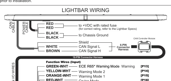
The lightbar requires connection to a +VDC power source. Ensure all power cables are routed to the vehicle battery using a factory pass-through. Splice the two RED wires together and install a user-supplied fuse before connecting to the battery. Connect the two BLACK wires to the vehicle chassis ground.
CAN Cable
Route the CAN cable to the CAN Controller Module and connect the CAN signal and shield wires to the 6-pin connector harness.
Function Wire Configuration
Input wires are activated by applying +VDC continuously. The system uses a precedence system [Px], where P1 is the highest priority. If multiple wires are activated simultaneously, the wire with the highest precedence overrides the others.
Warning Modes and Features
- ECE R65 Warning Mode: Apply +VDC to GREEN-WHT wire.
- Warning Mode 1: Apply +VDC to ORANGE-WHT wire.
- Warning Mode 2: Apply +VDC to YELLOW-WHT wire.
- Cruise Mode: Apply +VDC to RED-WHT wire.
- Full Front Flood: Apply +VDC to YELLOW wire.
- Take-Down Light: Apply +VDC to PURPLE wire.
- Alley Lights: Apply +VDC to GREEN (Left) or BLUE (Right) wire.
- Traffic Arrow: Apply +VDC to WHITE (Left) or WHITE-BLK (Right) wire.
- Rear Wig-Wag: Apply +VDC to GREY-WHT wire.
- Low Power Operation: Apply +VDC to RED wire.
PC Programming
The lightbar functions can be customized via PC software, including light sensor dimming, flash patterns, flash groups/phases, light colors, traffic arrow patterns, and wire precedence.
Safety Warnings
- Do not use power wires as the activation switch.
- Ensure power wires are connected before activating function wires.
- Do not use high-pressure washers to clean the lightbar, as this may damage the unit and void the warranty.
Manufacturer information
Cell2
Practical help
Common problems
Lightbar malfunctions or resets to default settings
Ensure all connections are secure and correct; faulty connections may cause the lightbar to malfunction or reset.
Functions not working as expected
Check the precedence [Px] of the activated wires; higher precedence wires (e.g., P1) will override lower precedence wires if activated simultaneously.
Before use
- Ensure power wires are connected to +VDC with a user-supplied fuse.
- Connect black wires to vehicle chassis ground.
- Determine and test required functions before installation.
- Verify CAN cable connection to the CAN Controller Module.
- Ensure all function wires are connected according to their specific function.
Specs in practice
- Function Wires (Input)
- Activated by applying +VDC continuously.
- Precedence [Px]
- Determines priority; P1 is the highest order and overrides lower precedence wires.
Images and diagrams
- The wiring diagram illustrates the 18-pin connector harness and the CAN cable connection.
- Input wires are color-coded for specific functions like Warning Modes, Cruise, and Traffic Arrow.
Model compatibility
- Requires +VDC power source.
- Compatible with CAN Controller Module.
- Warning Cut-off does not affect Take-Down Light, Alley Light, or Traffic Arrow functions.

Manual page author
David Miller
Documentation analyst
Organizes user manual content into clear summaries, with attention to model details, product context, and everyday usability.