Lighting / Decorative Lighting
Installation Manual for Tivoli Bare Step Premium Step Light
Comprehensive installation and maintenance guide for the Tivoli Bare Step Premium Step Light. Includes detailed wiring instructions, wire size selection charts, and procedures for light tube removal and replacement.
Table of contents
Manual images
Click an image to enlargeQuick guide from the manual
The Tivoli Bare Step is an aluminum step light designed for hard surfaces like concrete or wood. It is intended for both indoor and outdoor use. Important: This system must be installed by a certified professional. It requires a Class 2 12V DC transformer. Using any other power source will damage the fixture and void the warranty.
Installation tools and requirements
Before beginning, ensure you have the following tools:
- Tube caulk gun
- Extrusion Adhesive (ADH-MB-75AM-10)
- Concrete screws (TM-3/16, included)
- 1/4 inch double-sided tape
- 5/32 inch concrete drill bit
Installation steps
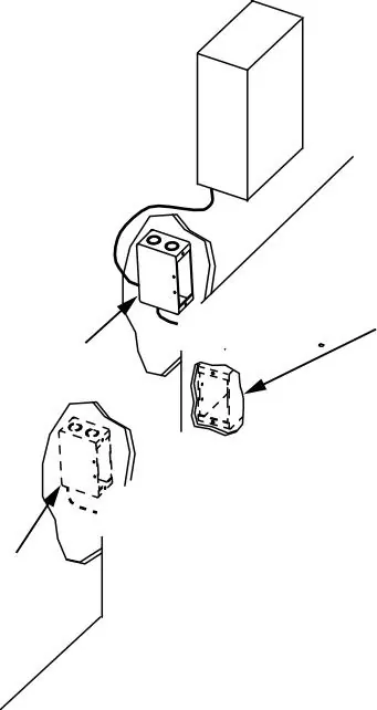
- Locate components: Identify the junction box and transformer locations, preferably during the construction phase.
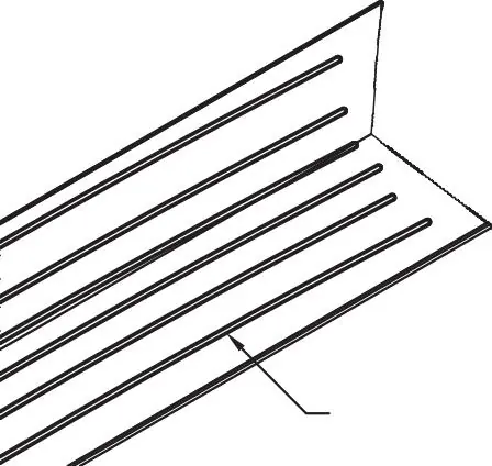
- Prepare the step: Drill pilot holes 3 inches from both ends and approximately every 12 inches along the top of the step.
- Apply adhesive: Apply adhesive to the underside of the Bare Step extrusion.
- Mounting: Place the unit on the edge of the step. Drill into the concrete through the pre-drilled holes using the 5/32 inch drill bit.
- Secure: Add a countersink to the holes and install the concrete screws.
- Wiring: Make the necessary wiring connections.
Wire size selection
To ensure the Class II lighting system operates correctly and to minimize voltage drop, select the appropriate wire gauge based on the distance from the power supply:
- 18 Gauge: Max 90 feet
- 16 Gauge: Max 95 feet
- 14 Gauge: Max 100 feet
- 12 Gauge: Max 105 feet
Light tube maintenance
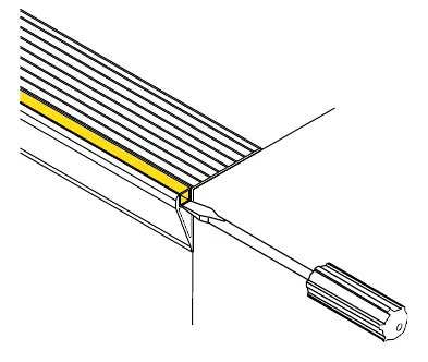
Removal: Turn off the power. Disconnect wiring. Use a small screwdriver to pry up the light tube from the open end, continuing along the length until free.
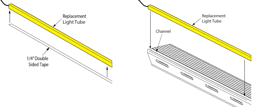
Replacement: Clean all surfaces inside the channel with denatured alcohol. Apply 1/4 inch double-sided tape to the bottom of the new light tube. Insert the tube into the channel, ensuring the end aligns with the extrusion edge. Press down lightly to ensure adhesion and re-wire the connections.
Practical help
Common problems
Voltage drop causing performance issues
Select the correct wire gauge based on the distance from the power supply to the fixture (refer to the wire size selection chart).
Risk of electrical shock
Always turn off the power before performing any installation, wiring, or maintenance tasks.
Damage to fixture or voided warranty
Use only listed Class 2 12V DC transformers. Do not use other power sources.
Before use
- Verify all package contents.
- Ensure power is turned off before starting installation.
- Consult local and national electrical codes.
- Ensure you have a Class 2 12V DC transformer.
- Confirm the mounting surface is hard (concrete or wood).
Specs in practice
- Class 2 12V DC
- The required power supply type to prevent damage and ensure safety.
Images and diagrams
- The junction box diagram illustrates the remote power supply connection and the option to use a junction box for each individual step unit.
- The adhesive application diagram shows the required 3/8 inch bead minimum on the underside of the extrusion.
Model compatibility
- Designed for installation on hard surfaces such as concrete or wood.
- Suitable for both indoor and outdoor applications.

Manual page author
Michael Turner
Technical manual editor
Reviews PDF manuals for structure, safety notes, and practical product details so readers can find the right information quickly.