General / Other Manuals
User Manual for CLAS DM 0600BL Semi-Automatic Tire Changer
Quick guide for the CLAS DM 0600BL semi-automatic tire changer, covering installation, operation, maintenance, and safety procedures.
Table of contents
Manual images
Jump to the sectionQuick guide from the manual
The CLAS DM 0600BL is a semi-automatic tire changer designed for cars, vans, light trucks, and motorcycles. It handles rim diameters from 10 to 21 inches and tire widths from 3 to 12 inches. This document provides essential instructions for installation, safe operation, and periodic maintenance to ensure optimal performance and longevity.
Installation and setup
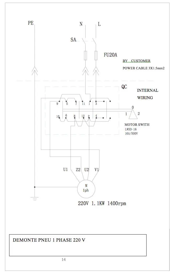
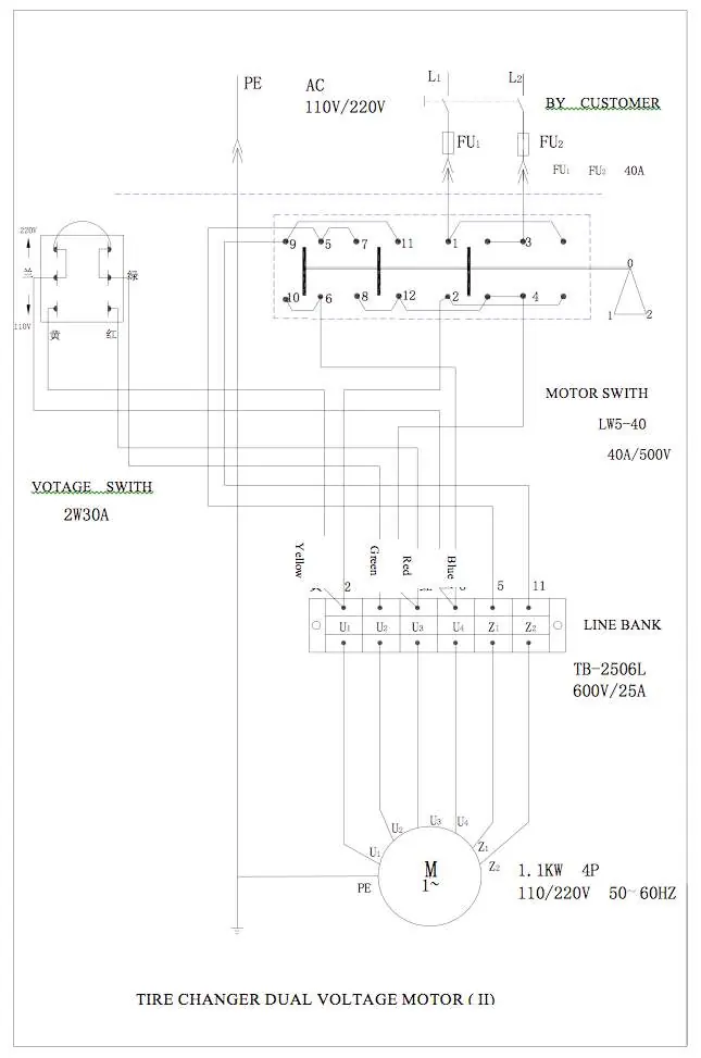
Installation must be performed by trained and qualified technicians. Ensure the machine is placed on a solid, level surface with adequate lighting. The machine requires an electrical connection (230V) and a compressed air supply (8-10 bar). For 3-phase motors, verify the turntable rotates clockwise; if it rotates counter-clockwise, swap two phases in the plug.
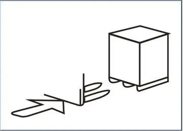
- Unpack the machine and verify all components are present.
- Secure the column to the body using the provided bolts.
- Install the vertical shaft spring and assemble the hand wheel.
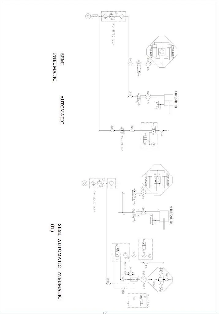
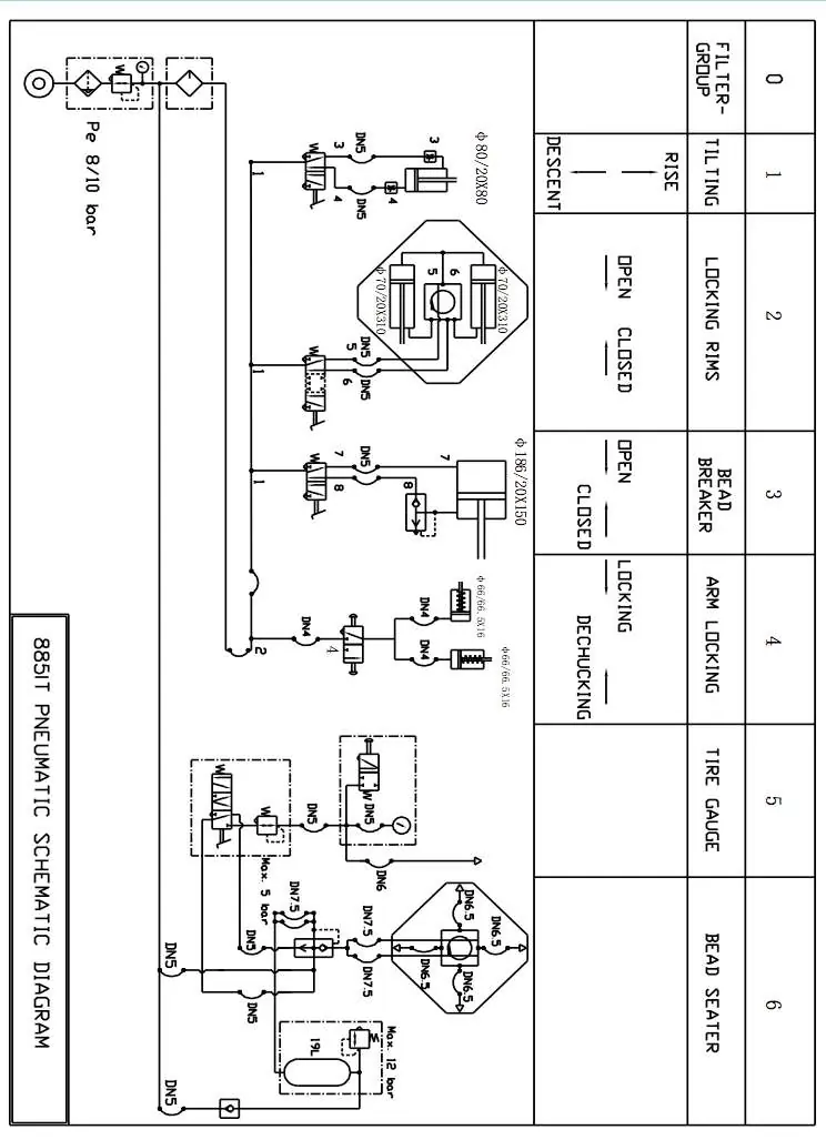
- Connect the air source to the separator and adjust the pressure to 8-10 bar.
- Check the pneumatic oil level; it should drop one drop every 5-6 pedal presses.
Operation
Before operation, ensure the working area is clean and the operator is wearing appropriate protective gear (gloves, safety glasses). Never place hands or limbs between moving parts, the tire, and the rim during operation.
Demounting
- Deflate the tire completely and remove wheel weights.
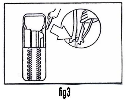
- Place the tire between the bead breaker blade and the rubber pad.
- Step on the bead breaking pedal to separate the bead from the rim.
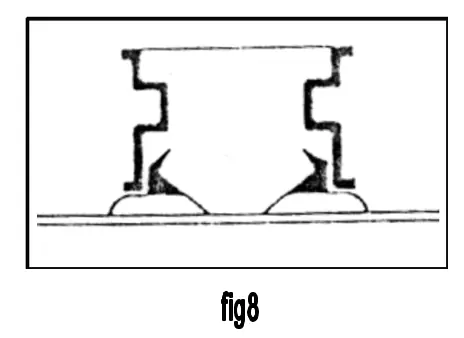
- Mount the rim on the turntable and secure it using the appropriate locking method (outside or inside).
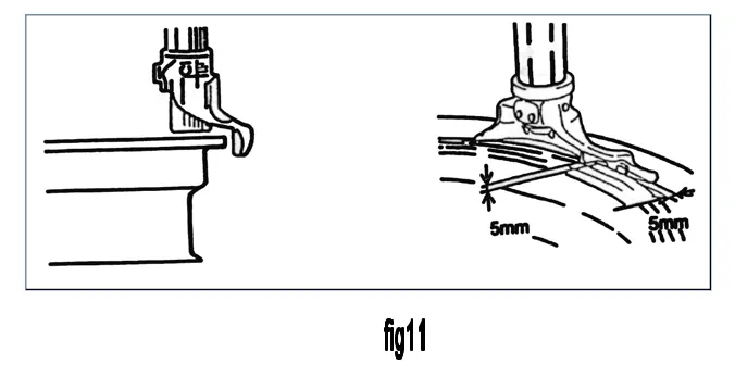
- Position the mount/demount head 4-5mm from the rim edge and lock the arm.
- Use the lever to lift the bead onto the head and rotate the turntable to demount.
Mounting
- Lubricate both sides of the tire and rim.
- Place the demount head on the rim edge and align the air valve.
- Position the tire bead under the head and rotate the turntable to mount the tire.
Maintenance
Regular maintenance is critical for safety and machine reliability. Always disconnect power and air sources and release residual pressure before performing maintenance.
- Clean and lubricate the turntable and clamps weekly with diesel oil.
- Check the air-container oil level periodically and refill with #20 oil if necessary.
- Regularly check and tighten all bolts and connectors.
- Keep the horizontal arm clean and lubricated for smooth movement.
- Drain water from the air compressor system regularly.
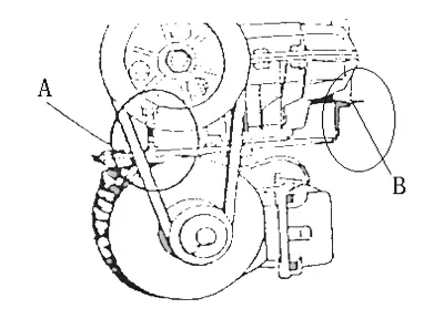
- Check and adjust the driving belt tension as needed.
Safety warnings
- Never place hands between the tire and the rim during inflation.
- Do not stand behind the machine during operation.
- Wear protective glasses when inflating tires.
- Keep long hair, loose clothing, and jewelry away from moving parts.
- Do not modify the machine or adjust internal pressure valves.
Manufacturer information
CLAS EQUIPEMENTS
Practical help
Common problems
Turntable rotates in the wrong direction (3PH models)
Reverse any two of the wires in the three-phase plug.
Insufficient grip or bead breaking force
Check that the operating pressure is between 8-10 bar (110-140 Psi). If lower, check the air hose or compressor.
Pneumatic oil dropping too fast or too slow
Adjust the index on the air regulator using a screwdriver.
Before use
- Ensure the machine is fixed securely to the ground.
- Verify the air pressure is set to 8-10 bar.
- Check that all pedals are in their original position.
- Ensure the working area is clean and well-lit.
- Wear appropriate safety gear, including gloves and glasses.
Specs in practice
- Operating pressure
- 8-10 bar (110-140 Psi) is required for optimal performance.
- Rim diameter
- Supports 10-21 inches; outside locking 10-18 inches, inside locking 12-21 inches.
Images and diagrams
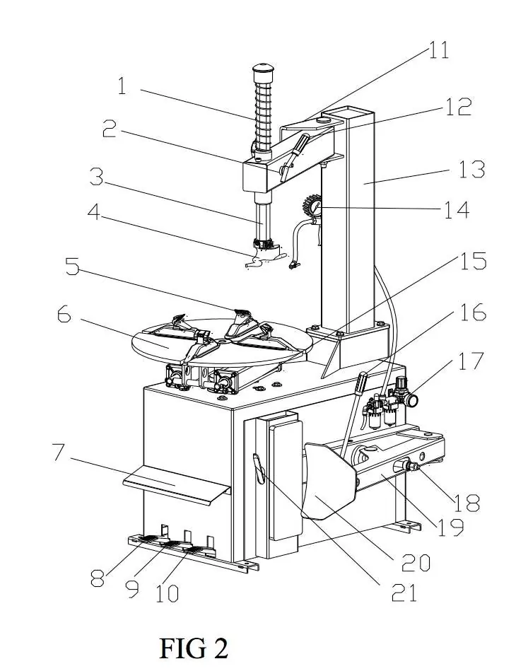
- Fig 2: Identifies all major components including pedals, turntable, and arms.
- Fig 11: Shows the correct 4-5mm distance between the mount/demount head and the rim.
- Fig 21: Illustrates the motor belt tension adjustment procedure.
Model compatibility
- Designed for cars, vans, light trucks, and motorcycles.
- Suitable for Run Flat tires.
- Outside locking is recommended for aluminum alloy rims.

Manual page author
David Miller
Documentation analyst
Organizes user manual content into clear summaries, with attention to model details, product context, and everyday usability.