Power / Power Strips
Installation Guide for CMS Electracom VERO 140W USB C Charging Unit
Step-by-step installation instructions for the CMS Electracom VERO 140W USB C Charging Unit. This guide covers desk cutout requirements, mounting procedures, and electrical connection steps.
Table of contents
Quick Installation Overview
The VERO 140W USB C Charging Unit is designed for integration into desks or joinery. Proper installation requires a precision cutout based on the specific technical drawing for your model. The process involves securing the USB unit from below and installing the power undercarriage around it.
Installation Steps
- Prepare the Cutout: Create a precision machine cutout in the desk or joinery according to the size and tolerance specifications found in the technical drawing for your selected model.
- Install USB Cables: Insert the USB cables into the keystone jacks, ensuring the correct alignment of the connections.
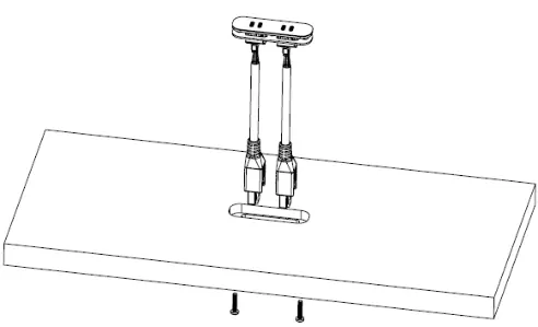
- Secure the Unit: Insert the unit into the cutout and secure it from below using the provided screws. Do not over-tighten the screws to avoid damage.
- Install Power Undercarriage: Position the power undercarriage equally around the USB unit cutout and secure it using the correct length self-tapping screws.
Electrical Connections
Once the unit is mounted, follow these steps to complete the electrical setup:
- Remove the access hatch to gain visibility and access to the USB charger ports.
- Plug the 12-pin connector into the keystone USB module.
- Replace the access hatch.
- Connect the tag connector to the softwiring leads or starter lead to power the unit.
Practical help
Common problems
Unit does not fit in the desk cutout
Ensure the cutout matches the exact size and tolerance listed on the technical drawing for your specific model.
Risk of damaging the unit during installation
Do not over-tighten the screws when securing the unit from below.
Before use
- Verify the technical drawing for correct cutout dimensions.
- Ensure you have the correct length self-tapping screws for the power undercarriage.
- Check that USB cables are correctly aligned in the keystone jacks before insertion.
- Confirm access to the underside of the desk for mounting.
Specs in practice
- 12-pin connector
- The specific connector required to link the USB module to the power source.
- Tag connector
- The connector used to link the unit to softwiring leads or a starter lead.
Images and diagrams
- The guide illustrates the sequence of inserting the unit into the desk cutout and securing it from below.
- The diagrams show the placement of the power undercarriage around the USB unit.
- The final diagram details the connection of the 12-pin connector and the tag connector.
Model compatibility
- Requires specific technical drawing for cutout dimensions.
- Compatible with softwiring leads or starter leads.

Manual page author
David Miller
Documentation analyst
Organizes user manual content into clear summaries, with attention to model details, product context, and everyday usability.