Furniture / Beds & Mattresses
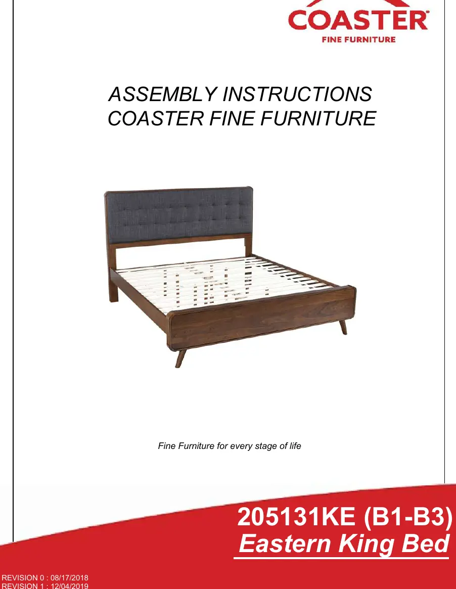
Assembly Instructions for Coaster Eastern King Bed 205131KE
Comprehensive assembly guide for the Coaster Eastern King Bed (Model 205131KE). This manual includes a complete parts list, hardware identification, step-by-step assembly instructions, and product dimensions.
Quick answers from the manual
Quick answer
- This document provides step-by-step assembly instructions for the Coaster Eastern King Bed (Model 205131KE). It includes a parts list, hardware identification, and assembly steps. p. 1, 9
Key actions
- Sort all hardware by size before beginning assembly. p. 2, 4
- Assemble the headboard by attaching legs (BM, CM) to the panel (AM) using bolts and the provided Allen wrench. p. 5
First start
- Prepare the assembly area and verify all parts from boxes B1, B2, and B3 are present. p. 2
Problems and fixes
Broken or defective parts
Do not attempt to repair or modify; contact the store immediately.
p. 2Technical specifications
| Parameter | Value | Meaning | Pages |
|---|---|---|---|
| Inner Size | 76.00"W x 81.00"D | Mattress support dimensions | p. 10 |
Where to find it in the PDF
- Assembly Instructions p. 1, 9
- Parts Identification p. 2, 3
- Hardware Identification p. 4
- Dimensions p. 10
Table of contents
Manual images
Click an image to enlargeQuick guide from the manual
This document provides instructions for assembling the Coaster Eastern King Bed (Model 205131KE). The estimated assembly time is 35 minutes. Before beginning, ensure you have a Phillips head screwdriver, as it is required but not provided. Please verify that all parts and hardware from boxes B1, B2, and B3 are present before starting.
Parts Identification
The bed components are divided into three boxes:
- B1 (Box 1): Headboard Panel (AM), Left Headboard Leg (BM), Right Headboard Leg (CM), Headboard Bottom Rail (DM).
- B2 (Box 2): Footboard Panel (EM), Footboard Leg (FM).
- B3 (Box 3): Bed Rail (GM), Center Rail (HM), Center Rail Support with Leveler (IM), Roll Slat (JM), Bed Slat Support with Leveler (KM).
Hardware Identification
The hardware pack is located in box B3. Required items include:
- Allen Wrench (M4 x 110mm)
- Short Bolt with Washer (M6 x 25mm)
- Medium Bolt with Washer (M6 x 45mm)
- Long Bolt with Washer (M6 x 60mm)
- Short Flat Head Screw (M4 x 20mm)
- Long Flat Head Screw (#8 x 1 1/8")
- Hex Nut (M6)
- U Bracket
- Wrench
Assembly Steps
Follow these steps in the numbered sequence to ensure proper assembly:
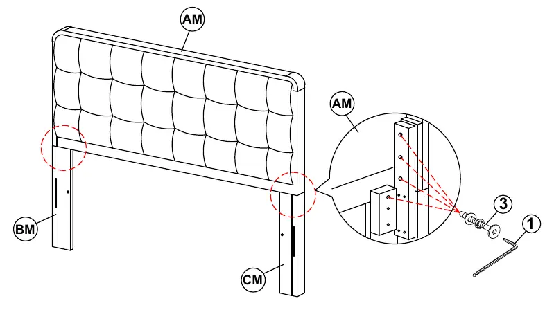
- Step 1: Attach the Headboard Legs (BM, CM) to the Headboard Panel (AM) using the Medium Bolts (3) and Allen Wrench (1).
- Step 2: Attach the Headboard Bottom Rail (DM) to the legs using Medium Bolts (3) and Allen Wrench (1).
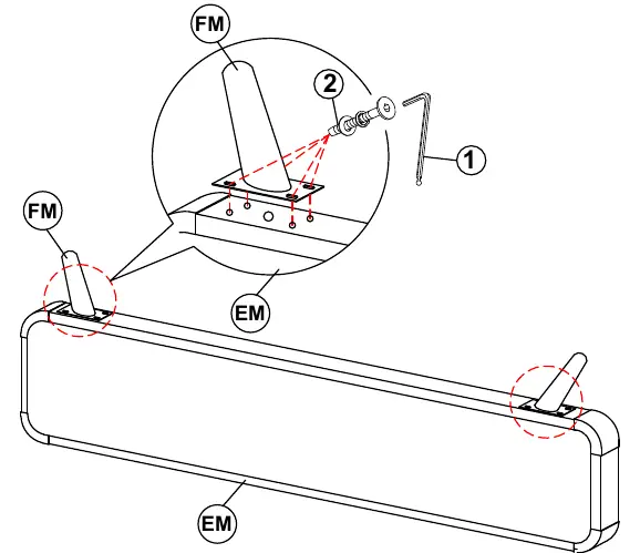
- Step 3: Attach the Footboard Legs (FM) to the Footboard Panel (EM) using Short Bolts (2) and Allen Wrench (1).
- Step 4: Connect the Bed Rails (GM) to the Headboard and Footboard assemblies.
- Step 5: Secure the Bed Rails to the Headboard and Footboard using Long Flat Head Screws (5) and U Brackets (8).
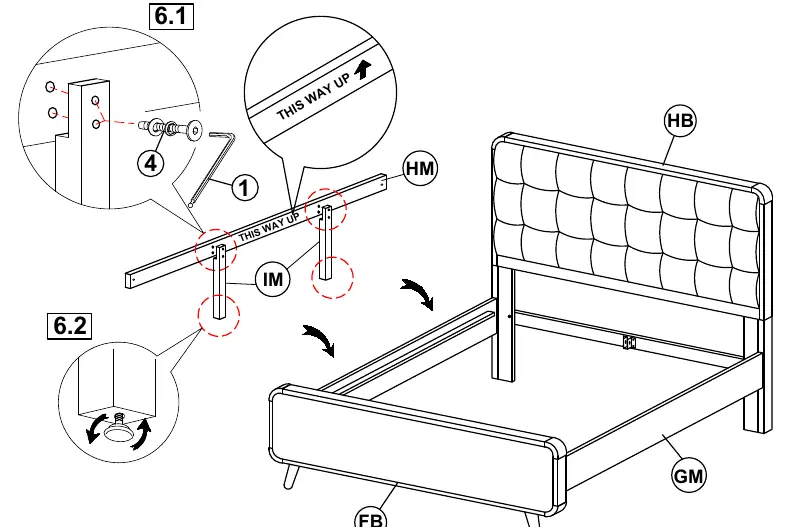
- Step 6: Assemble the Center Rail (HM) with the Center Rail Supports (IM) using Long Bolts (4) and Allen Wrench (1). Ensure the "THIS WAY UP" label is oriented correctly.
- Step 7: Secure the Center Rail assembly to the Headboard and Footboard using Hex Nuts (7), Medium Bolts (3), and the provided Wrench (9).
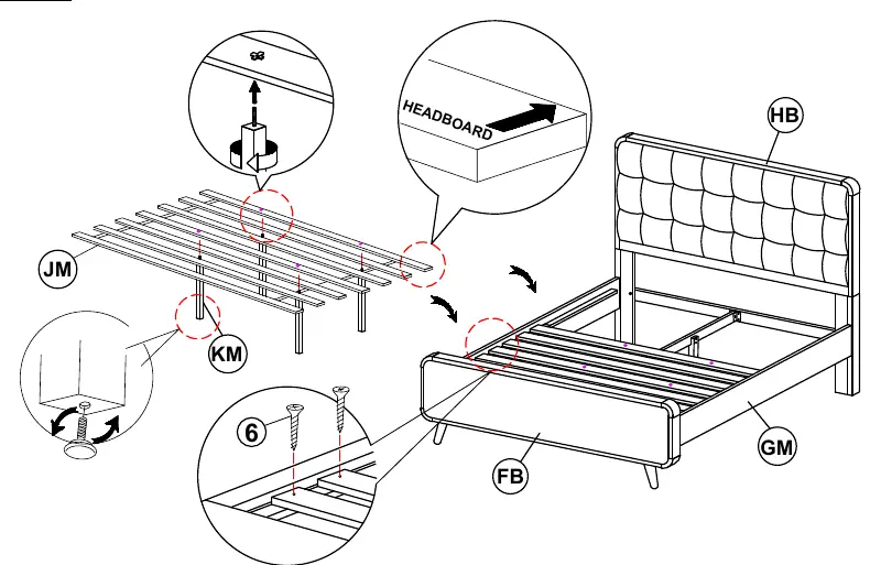
- Step 8: Place the Roll Slats (JM) onto the bed frame. Attach the Bed Slat Supports (KM) to the slats and secure the slats to the bed rails using Long Flat Head Screws (6).
Dimensions
The inner mattress support size is 76.00 inches wide by 81.00 inches deep. A dimension tolerance of ±5% applies.
Safety
Do not attempt to repair or modify parts that are broken or defective; contact the store immediately. This product is intended for home use only and not for commercial establishments.
Manufacturer information
Coaster Fine Furniture
Practical help
Common problems
Missing hardware or parts
Check all boxes (B1, B2, B3) and sort hardware by size before starting assembly.
Damaged parts
Do not attempt to repair or modify broken parts; contact the store immediately.
Before use
- Remove all hardware from the box and sort by size.
- Verify all parts listed in the Parts Identification section are present.
- Ensure you have a Phillips head screwdriver (not provided).
- Clear enough space for assembly.
- Follow the numbered sequence for assembly.
Specs in practice
- Assembly Time
- Approximately 35 minutes
Images and diagrams
- The manual uses numbered steps corresponding to specific hardware and parts.
- Red circles in diagrams indicate connection points.
- Arrows indicate direction of assembly or orientation.
Model compatibility
- For home use only; not intended for commercial establishments.

Manual page author
David Miller
Documentation analyst
Organizes user manual content into clear summaries, with attention to model details, product context, and everyday usability.