General / Other Manuals
Cobra 148GTL-DX CB Radio User Manual
User manual for the Cobra 148GTL-DX 120-channel mobile radio. Includes installation, antenna SWR tuning, operating instructions for AM/FM/SSB/CW modes, and microphone wiring diagrams.
Table of contents
Manual images
Jump to the sectionQuick Guide
The Cobra 148GTL-DX is a 120-channel mobile radio supporting AM, FM, SSB (USB/LSB), and CW modes. It features a Phase Lock Loop (PLL) synthesizer for frequency control. Before operation, ensure the antenna is properly tuned and the power source is connected correctly.
Installation
Location: Choose a location in your vehicle that is convenient for operation and does not interfere with the driver or passengers. The unit is typically mounted below the dash.
Power Connection: Connect the red wire (with fuse) to a +13.8V DC source (typically an accessory contact on the ignition switch). Connect the black wire to a solid chassis ground.
Antenna: Use a standard 50-ohm antenna system. The radio uses a standard SO239 connector. If mounting on a non-metal surface, ensure a separate ground wire is run to the vehicle chassis.
Antenna Tuning (SWR)
Proper SWR tuning is critical for performance. The ideal SWR is 1.5 or below.
- Set the radio to Channel 21 (Mid band).
- Press the PTT switch and use the SWR CAL control to adjust the meter to the CAL position.
- Switch the meter to SWR and read the value.
- If the reading is above 3, antenna adjustment is required.
- Adjust the antenna length (by extending or cutting in 1/8" increments) until the lowest SWR is achieved.
- Verify the SWR on Channel 1 (Low band) and Channel 40 (Hi band); the readings should be similar.
Operation
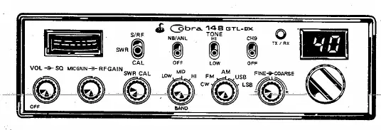
Controls: The front panel includes volume, squelch, RF gain, mic gain, and mode selection (AM/FM/USB/LSB/CW). Use the Squelch control to eliminate background noise by turning it clockwise until the noise just disappears.
Receiving SSB Signals: SSB signals require the receiver to be in the same mode (USB or LSB) as the transmitter. If the signal is unintelligible, adjust the Voice Lock control to fine-tune the frequency.
Transmitting: Select the desired channel, set the Mic Gain fully clockwise, and press the PTT switch on the microphone to speak.
Microphone Installation
The radio uses a 4-wire dynamic microphone. If replacing or installing an alternate microphone, follow the wiring standard:
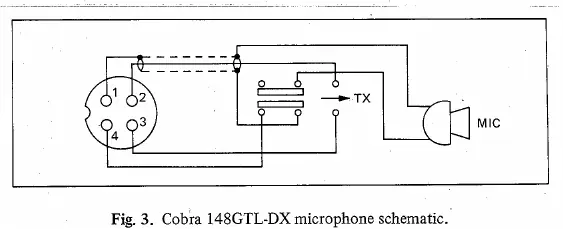
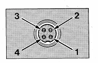
- Pin 1: Audio Shield
- Pin 2: Audio Lead
- Pin 3: Transmit Control
- Pin 4: Receive Control
Ensure all leads are cut to the same length, stripped, and tinned before soldering to the pins.
Maintenance
If the radio fails to operate, check the power connections, antenna SWR, and microphone wiring. If problems persist, refer to the warranty service instructions provided in the manual. Do not attempt to operate the unit by connecting directly to 120V AC without the optional power converter.
Manufacturer information
Cobra Electronics
Practical help
Common problems
High SWR reading
Adjust antenna length or check grounding/cabling. Ensure SWR is 1.5 or below.
Ignition noise interference
Use the ANL/NB controls on the front panel to reduce impulse noise.
SSB signal unintelligible
Ensure the receiver is in the same mode (USB/LSB) as the transmitter and adjust the Voice Lock control.
Before use
- Ensure 13.8V DC power source is connected.
- Verify antenna is properly connected to the SO239 connector.
- Check that all doors are closed when tuning the antenna.
- Ensure microphone is connected.
- Verify the mode switch is set to the desired operation (AM/FM/SSB/CW).
Images and diagrams
- Microphone wiring diagram shows pinout for 4-wire cables.
- SWR tuning procedure involves checking channels 1 and 40.
Model compatibility
- Requires 13.8V DC power.
- External speaker must have 8 ohms impedance.
- Requires optional CA-20 Power-Pak for 120V AC base station operation.

Manual page author
Emily Carter
User documentation editor
Prepares concise manual descriptions and highlights the most useful setup, operation, and maintenance information for readers.