HVAC / Air Conditioners
Installation Manual for Comfortstar CC-VAC VRF Outdoor Unit
Professional installation guide for Comfortstar CC-VAC VRF outdoor units. This manual covers mounting, foundation requirements, refrigerant piping design, electrical wiring, system configuration via dialing codes, and trial run procedures.
Quick answers from the manual
Quick answer
- This is an installation manual for Comfortstar CC-VAC VRF outdoor units. It provides comprehensive instructions for mounting, refrigerant piping, electrical wiring, system configuration via dialing codes, and trial run procedures. p. 1
Key actions
- Install the outdoor unit on a level, stable foundation with sufficient clearance. p. 3, 4
- Perform refrigerant piping and tightness testing with nitrogen. p. 7, 9
- Configure system settings using the dialing codes (SW switches). p. 12
First start
- Perform a full system inspection, including checking refrigerant connections, electrical wiring, and vacuuming the system before the trial run. p. 16
Show 4 more answers Show less
Problems and fixes
Refrigerant leakage
Check connections, perform tightness test, and ensure proper ventilation.
p. 16Maintenance and reset
- Dialing code settings cannot be performed unless the power supply is cut off. p. 12
Technical specifications
| Parameter | Value | Meaning | Pages |
|---|---|---|---|
| Refrigerant | R410A | Refrigerant type | p. 16 |
| GWP | 2087.5 | Global Warming Potential | p. 16 |
Where to find it in the PDF
- Installation and Foundation p. 3, 4, 5
- Refrigerant Piping p. 7, 8, 9, 10
- Electrical Wiring p. 13, 14, 15
- Dialing Codes p. 12
Table of contents
Manual images
Click an image to enlargeQuick guide from the manual
This document provides essential installation instructions for the Comfortstar CC-VAC VRF outdoor unit. Installation must be performed by a professional worker. Key steps include site preparation, foundation construction, refrigerant piping, electrical wiring, and system configuration using dialing codes.
Safety precautions
- Installation must be performed by a professional.
- Ensure the foundation is strong enough to support the unit.
- Do not install in areas with flammable gas leakage risks.
- Ensure proper electrical grounding and use specified power cables.
- Refrigerant leakage can be hazardous; ensure proper ventilation and detection if necessary.
Installation of outdoor unit
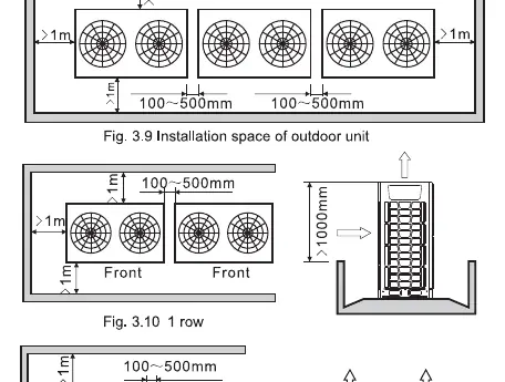
The unit must be installed on a level, stable foundation. Ensure there is sufficient space for maintenance and airflow. Refer to the dimensions provided in the manual for specific models (8HP to 24HP).

- Hoisting: Use two ropes of at least 8m for balanced lifting.
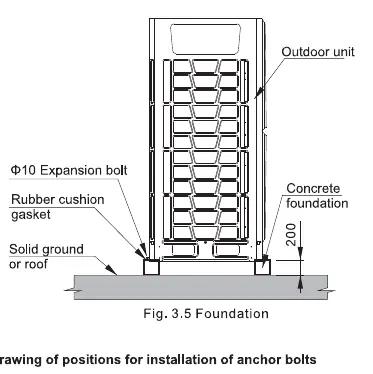
- Foundation: Must be concrete or cement, fully leveled, and include drainage ditches.
- Anchor bolts: Follow the specific positioning dimensions provided in the manual.
Refrigerant pipe design
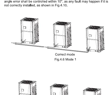
Proper piping is critical for system performance. Ensure the refrigerant tube length and height differences are within the specified limits. Use the provided tables to select the correct tube diameters based on the capacity of the downstream indoor units.
Electrical wiring
Power supply and signal cables must be installed according to the wiring diagrams. Use shielded cables for signal transmission to prevent interference. Ensure the power supply capacity matches the requirements for the specific unit capacity.
Dialing code settings
The system configuration is managed via dialing codes (SW switches). These settings control functions such as static pressure, night silent mode, and outdoor unit addressing. Ensure the power is cut off before changing any dialing code settings.
Trial running
Before starting the system, perform a thorough inspection:
- Check that all refrigerant tubes and communication lines are correctly connected.
- Verify the power supply voltage is within ±10% of the rated voltage.
- Ensure the system has been vacuumed and tested for tightness.
- Record the system configuration on the nameplate.
Practical help
Common problems
Refrigerant leakage
Check all pipe connections, ensure tightness, and perform a pressure test with nitrogen.
Electrical interference
Use 2-core shielded cable for signal lines and ensure proper grounding.
Unit instability
Ensure the foundation is level and the unit is tightly secured with anchor bolts.
Before use
- Verify the unit is free from transport damage.
- Ensure the installation site has sufficient space for airflow and maintenance.
- Confirm the power supply matches the unit requirements.
- Check that all refrigerant pipes are properly insulated.
- Ensure the system has been vacuumed and pressure-tested.
- Verify all dialing code settings are configured correctly.
Show more Show less
Specs in practice
- Power Supply
- 208-230V 3N~ 60Hz
- Pressure Test
- 4.0MPa (40kgf/cm²) for 24 hours
Images and diagrams
- Fig 3.5: Foundation construction details including rubber cushion and expansion bolts.
- Fig 3.9-3.13: Installation space requirements and barrier clearance.
- Fig 4.6-4.8: Correct and incorrect refrigerant pipe installation modes.
- Fig 5.7: Electrical wiring diagram for master and slave units.
Model compatibility
- Designed for ALL DC Inverter VRF systems.
- Requires professional installation.
- Not for use in environments with high risk of flammable gas leakage without proper precautions.

Manual page author
Michael Turner
Technical manual editor