HVAC / Air Conditioners
Installation and Maintenance Manual for Temperzone ISD 211LYX Ducted Split System
Comprehensive installation and maintenance guide for the Temperzone ISD 211LYX ducted split system. Includes detailed instructions on unit mounting, R32 refrigerant handling, electrical wiring, system commissioning, and troubleshooting.
Quick answers from the manual
Quick answer
- This manual provides installation, maintenance, and commissioning instructions for the Temperzone ISD 211LYX ducted split system, including R32 refrigerant handling, wiring, and start-up procedures. p. 1, 4, 5
Key actions
- Install condensate drain trap p. 1
- Adjust indoor fan speed p. 4
- Start compressor in commissioning mode p. 4
First start
- Ensure thermostat is OFF, leave unit off for 4 hours to drive refrigerant out of the compressor, then switch on power. p. 4
Show 4 more answers Show less
Problems and fixes
Indoor unit spitting or leaking water
Check drain trap, vent, and slope.
p. 5
Air conditioner runs excessively
Check for open windows/doors, blocked outdoor coil, or leaks in ductwork.
p. 6Maintenance and reset
- Reset controller by cycling mains power off and on again after changing DIP switch settings. p. 4
Technical specifications
| Parameter | Value | Meaning | Pages |
|---|---|---|---|
| Vacuum Pressure | 500 microns | Required vacuum level for evacuation. | p. 2 |
| Communication Cable | 22-26 AWG | Recommended wire gauge for shielded twisted pair cable. | p. 3 |
Where to find it in the PDF
- General Installation p. 1
- Refrigeration p. 2
- Start-up Procedure p. 4, 5
- Maintenance p. 5
- Troubleshooting p. 5, 6
- Commissioning Check List p. 8
Table of contents
Manual images
Click an image to enlargeQuick Guide from the Manual
This document provides essential installation and maintenance procedures for the Temperzone ISD 211LYX ducted split system. Important Safety Warning: These units use R32 refrigerant (Class A2L), which is mildly flammable. The system must be installed and stored in a well-ventilated space away from ignition sources. Always follow local health and safety regulations and ensure all work is performed by qualified technicians.
Installation
The installation process involves both the indoor (ISD) and outdoor (OSA) units.
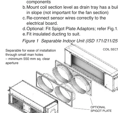
Indoor Unit Positioning and Mounting
- Use the supplied 'L' shape brackets to hang the unit on threaded rods or suspension wires.
- For separable units (ISD 171/211/251), the coil section and fan section can be separated for easier maneuvering.
- Mount the coil section level to ensure the drain tray functions correctly.
- Fit insulated ducting according to best practices to minimize noise and ensure proper airflow.
Drains
- Install the main drain tray pipe with a minimum slope of 20mm per meter (1 in 50).
- A 'U' trap is required for the condensate drain.
Outdoor Unit
- Ensure adequate clearances for airflow and servicing as per the specification sheet.
- Avoid installing where fan blades face prevailing winds.
- Use rubber pads or optional anti-vibration mounts to minimize vibration transmission.
Refrigeration
All refrigeration work must be performed by a technician with a current Refrigerant Handling Licence.
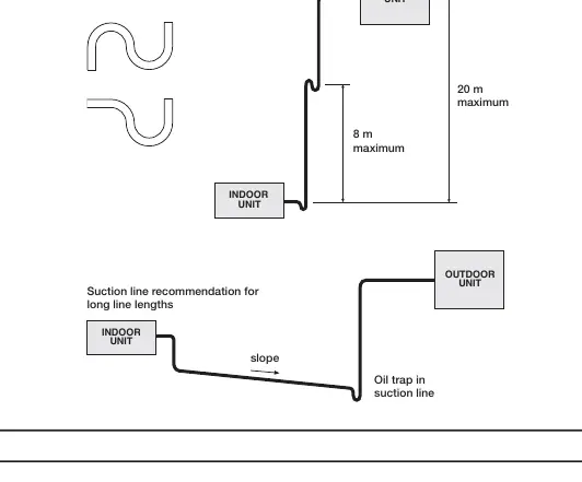
- Piping and Brazing: Use clean, sealed refrigeration-grade piping. Insulate both suction (gas) and liquid lines.
- Evacuation: Evacuate the indoor unit and interconnecting pipework to a vacuum pressure of 500 microns and hold for 15 minutes.
- Charging: Calculate additional refrigerant based on line length. Do not exceed the maximum charge specified.
Wiring
- Power: All wiring must be fitted by qualified persons. The unit requires a dedicated circuit breaker.
- Control: Communication wiring between indoor and outdoor units must be shielded twisted pair cable (22-26 AWG). Keep communication cables at least 300mm away from mains power cables to minimize interference.
Start-up Procedure
- Pre-start: Ensure the thermostat is OFF. Leave the unit off for 4 hours before starting to drive refrigerant out of the compressor.
- Fan Adjustment: Fan speeds can be adjusted via the UC8 controller or the SAT-3 thermostat.
- Compressor: Use the SW3 push button on the UC8 controller to enter commissioning mode ('c') to reduce waiting times during start-up.
Maintenance
- Weekly (First 4 weeks): Check air filters, condensate drains, and compressor compartment for oil stains (indicating leaks).
- Monthly: Clean or replace air filters.
- Six Monthly: Check fan/motor mountings, electrical connections, and heat exchanger coils.
- Yearly: Inspect refrigerant piping for chafing, check insulation, and clean outdoor coil fins.
Troubleshooting
- Water Leaks: Usually caused by poor drain trapping or incorrect slope.
- Heating Issues: Check for de-icing cycles or incorrect unit sizing.
- Temperature Variations: Check for drafts, bad air circulation, or incorrect BMS wiring.
Practical help
Common problems
Indoor unit spitting or leaking water
Check the drain trap, vent, and slope. Ensure the drain tray is installed correctly.
Unit does not deliver heating when needed
The unit may be in a de-icing cycle. Also, check if the unit is correctly sized for the building's heat loss.
Temperature varies significantly from setting
Check for drafts from diffusers, bad air circulation, or incorrect BMS wiring.
Before use
- Ensure both units are level.
- Verify refrigerant charge size is appropriate for the room size.
- Check that all electrical terminals are tight.
- Confirm the drain trap is fitted and tested.
- Ensure the thermostat is OFF and the unit has been off for 4 hours before initial start-up.
- Verify that all access panels are in place.
Show more Show less
Specs in practice
- R32 Refrigerant
- Mildly flammable refrigerant; requires specific handling and ventilation.
- Vacuum Pressure
- 500 microns; required for proper system evacuation.
- Communication Cable
- Shielded twisted pair, 22-26 AWG; essential for interference-free control.
Images and diagrams
- Figure 1: Shows the separable indoor unit components and mounting.
- Figure 2: Illustrates the correct condensate drain trap configuration with slope.
- Figure 3: Details the oil trap design required for long line lengths.
- Figure 4: Provides the connection wiring schematic for power and control.
Model compatibility
- Compatible with Temperzone TZT-100 and SAT-3 thermostats.
- Supports BMS control via dry contact, analog inputs, or Modbus over RS485.
- Do not connect an alternative thermostat to both the IUC and UC8 simultaneously.

Manual page author
David Miller
Documentation analyst