HVAC / Air Conditioners
Technical Specifications and Wiring Guide for Temperzone OPA 211RLTFYD Econex Pro
A comprehensive technical guide for the Temperzone OPA 211RLTFYD Econex Pro air conditioning unit, featuring detailed specifications, dimensions, clearance requirements, and complete electrical wiring schematics.
Quick answers from the manual
Quick answer
- The OPA 211RLTFYD is a 3-phase 400V AC air conditioning unit. It requires a 24-hour power supply for the control circuit and crankcase heaters and uses R32 refrigerant. p. 1
Key actions
- Ensure 24-hour power supply for control circuit p. 4
Technical specifications
| Parameter | Value | Meaning | Pages |
|---|---|---|---|
| Cooling capacity (net) | 19.9 kW | Net cooling output | p. 1 |
| Heating capacity | 19.7 kW | Heating output | p. 1 |
| Refrigerant | R32 | Refrigerant type | p. 1 |
Show 1 more answers Show less
Where to find it in the PDF
- Specifications p. 1
- Dimensions p. 2
- Wiring Schematic p. 3, 4
Table of contents
Manual images
Click an image to enlargeImportant Information
The Temperzone OPA 211RLTFYD Econex Pro is a high-capacity air conditioning unit. This document provides essential technical specifications and wiring schematics required for proper installation and maintenance. Important Note: The unit requires a 24-hour power supply for the control circuit and crankcase heaters to ensure proper operation.
Technical Specifications
The unit is designed for 3-phase power supply. Key specifications include:
- Cooling Capacity (net): 19.9 kW
- Heating Capacity: 19.7 kW
- Power Supply: 3 ph. 400V AC 50Hz + N + E
- Refrigerant: R32 (Charge: 4.75 kg)
- Compressor Type: Inverter scroll
- Net Weight: 299 kg
- Shipping Weight: 341 kg
- Recommended RCD: Type B, 30mA, 3 pole
Dimensions and Clearances
The unit requires specific clearances for airflow and maintenance access. Ensure the following minimum clearances are maintained:
- Top Clearance: 2000 mm
- Side Clearances: 1000 mm and 500 mm as indicated in the dimension diagrams.
- Floor Area: A minimum floor area of 12 m2 is required (@2.4m below ceiling diffuser).
Wiring and Electrical Installation
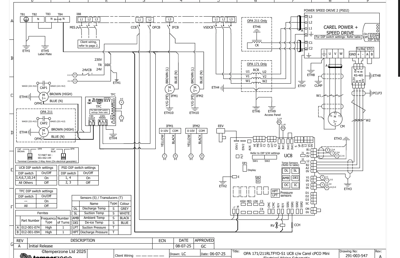
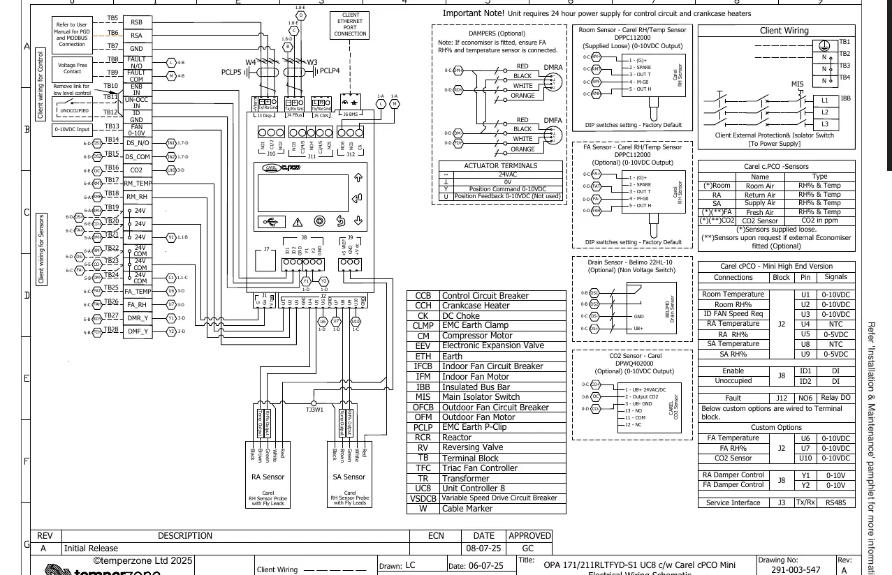
The document contains detailed electrical wiring schematics (Sheet 1 and 2). Key electrical considerations include:
- Control Circuit Breaker: Internal 4A.
- Running Amps (total system): 11.5 A/ph.
- Max. Running Amps (total system): 20.0 A/ph.
- Client Wiring: Refer to the provided wiring diagrams for connections to the UC8 controller, sensors (Room, Return Air, Supply Air, Fresh Air, CO2), and optional dampers.
- Sensors: The unit supports various sensors including Discharge Temp, Suction Temp, Ambient Temp, and De-ice Temp.
Practical help
Common problems
Unit fails to start or control circuit issues
Verify that the 24-hour power supply for the control circuit and crankcase heaters is active.
Incorrect sensor readings
Check wiring connections for sensors (Room, RA, SA, FA, CO2) against the provided wiring schematic, ensuring correct polarity and terminal block assignment.
Before use
- Ensure a 3-phase 400V AC 50Hz power supply is available.
- Verify that a Type B, 30mA, 3-pole RCD is installed.
- Confirm 24-hour power supply is connected to the control circuit and crankcase heaters.
- Check that minimum clearances (1000mm/2000mm) are maintained around the unit.
- Verify that the minimum floor area of 12m2 is available.
Show more Show less
Specs in practice
- Refrigerant R32
- The specific refrigerant type used in this unit; requires handling by qualified personnel.
- 3 ph. 400V AC
- The electrical power requirement for the unit; ensure the site supply matches this specification.
- Net Weight 299 kg
- The weight of the unit without packaging; ensure the mounting surface can support this load.
Images and diagrams
- The dimension diagram (Page 2) shows the physical footprint, mounting hole centers, and required service clearances.
- The wiring schematic (Page 3-4) details the connections for the UC8 controller, compressors, fans, and external sensors.
Model compatibility
- Compatible with Carel cPCO Mini controller.
- Supports optional dampers and CO2 sensors.
- Requires specific wiring for economiser if fitted.

Manual page author
David Miller
Documentation analyst