HVAC / Air Conditioners
Installation and Operation Manual for Friedrich 24-48K BTU Outdoor Condenser
Comprehensive installation and operation guide for Friedrich 24-48K BTU single-zone outdoor condensers. Includes critical safety protocols for R-454B refrigerant, wiring diagrams, piping installation, torque specifications, and test run...
Quick answers from the manual
Quick answer
- This manual provides installation and operation instructions for Friedrich 24k-48k BTU outdoor condensers using R-454B refrigerant. It covers safety, piping, wiring, and test run procedures. p. 1, 3, 10, 21
Key actions
- Install outdoor unit on a solid, level base with required clearances. p. 10, 11
- Perform refrigerant piping with proper flaring and torque tightening. p. 13, 14
- Perform vacuum pumping and leak testing before opening stop valves. p. 15, 16
First start
- Ensure all power is off, check insulation resistance, and preheat crankcase heater for 6 hours if cold. p. 21
Show 3 more answers Show less
Problems and fixes
Refrigerant leak
Check flare connections and brazed joints with leak detection foam.
p. 15, 16Technical specifications
| Parameter | Value | Meaning | Pages |
|---|---|---|---|
| Max. Refrigerant Charge (24K) | 126.53 oz (3587 g) | Maximum refrigerant charge amount | p. 10 |
| Max. Refrigerant Charge (36K) | 165.22 oz (4684 g) | Maximum refrigerant charge amount | p. 10 |
| Max. Refrigerant Charge (48K) | 256.2 oz (7263 g) | Maximum refrigerant charge amount | p. 10 |
Where to find it in the PDF
- Safety Precautions p. 1, 2, 3, 4
- Electrical Wiring p. 9
- Installation Instructions p. 10, 11, 12, 13
- Test Run p. 21
Table of contents
Manual images
Click an image to enlargeImportant Safety Information
This manual is intended for qualified personnel. The unit uses R-454B refrigerant, which is flammable. Strict adherence to safety protocols is required to prevent fire, explosion, or injury. Ensure the installation area is well-ventilated and free of ignition sources. Do not discharge refrigerant into the atmosphere. Always use a dedicated power line and ensure proper grounding.
Installation Location
Select a location that supports the unit's weight and allows for proper airflow. Avoid areas with:
- Flammable or explosive hazards (gas stations, mines).
- Corrosive or sulfurous environments.
- High-frequency electromagnetic interference (welding machines, medical equipment).
- Direct exposure to mineral oil fumes or spray.
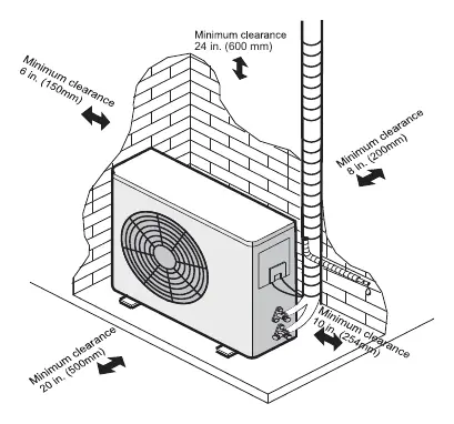
Maintain minimum clearances: 24 inches (600 mm) top, 6 inches (150 mm) side, 8 inches (200 mm) rear, and 20 inches (500 mm) front.
Outdoor Unit Installation
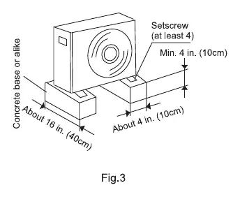
Fasten the unit securely to a concrete base or foundation using bolts. Ensure the unit is level to prevent noise and vibration. If installing in cold regions, do not use the drainage elbow as it may freeze. Ensure anchor bolts protrude no more than 3/4 inch (20 mm) to allow for service plate removal.
Refrigerant Piping
Use clean copper pipes. Ensure the pipe length is as short as possible to maintain capacity. If the indoor unit is lower than the outdoor unit and the height difference exceeds 32.8 ft (10 m), install a returned oil elbow on the vertical gas pipe every 20 ft (6 m).
Flaring and Connection:
- Cut pipes cleanly and remove all burrs.
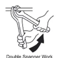
- Use a torque wrench to tighten flare nuts to specified values (e.g., 1/4" = 14.8 lb-ft, 3/8" = 29.5 lb-ft, 1/2" = 44.3 lb-ft, 5/8" = 59.0 lb-ft, 3/4" = 73.8 lb-ft).
- Apply a thin layer of refrigerant oil to the seat surface before tightening.
- Perform a nitrogen pressure test (550 psig / 3.79 MPa) to check for leaks before vacuuming.
Electrical Wiring
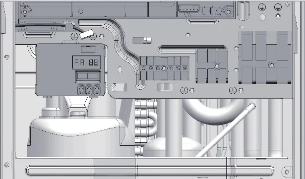
Turn off the main power supply and wait at least 3 minutes before performing any electrical work. Use a dedicated circuit breaker. Ensure the electrical insulation resistance is greater than 2 MΩ. Follow the provided wiring diagrams for specific indoor/outdoor unit configurations. For 36K models, connect the supplied Checker box to the control board.
Test Run
Before starting, verify:
- No structural damage.
- Fan impeller is clear.
- All screws are tightened.
- Stop valves are fully open.
- Grounding is secure.
After powering on, allow the crankcase heating belt to preheat for at least 6 hours if the ambient temperature is below 32°F (0°C). Perform a test run using the thermostat/wall controller.
Practical help
Common problems
Refrigerant leak
Check all flare connections and brazed joints using leak detection foam. Ensure flare nuts are tightened to the correct torque.
Unit not starting / Compressor failure
Verify power supply, check for correct phase sequence, and ensure the crankcase heater has preheated for 6 hours if ambient temperature is below 32°F.
Excessive noise or vibration
Ensure the unit is level on the foundation and that piping is not touching the building structure.
Before use
- Verify all power supplies are turned off before installation.
- Check that the fan impeller is centered and unobstructed.
- Confirm all flare nuts are tightened to the specified torque.
- Ensure stop valves are fully open.
- Verify electrical insulation resistance is > 2 MΩ.
- Confirm the crankcase heater has been energized for 6 hours if cold.
Show more Show less
Images and diagrams
- Clearance diagram: Shows minimum distances required around the unit for airflow.
- Wiring diagrams: Illustrate connections between outdoor unit, indoor unit, and power supply.
- Stop valve operation: Shows how to open/close valves using a hexagon wrench.
Model compatibility
- Compatible with Wall Mounted, Cassette, Concealed Ducted, and AHU indoor units.
- Requires R-454B compatible service tools.
- 24k outdoor unit requires an additional 7.05 oz (200g) charge when connected to an AHU.

Manual page author
Michael Turner
Technical manual editor