HVAC / Air Conditioners
Temperzone ISD 211LYX and OSA 211RLTFH Air Conditioner Specifications and Wiring Guide
Technical specifications, installation dimensions, and detailed wiring diagrams for the Temperzone ISD 211LYX indoor unit and OSA 211RLTFH outdoor unit. Includes DIP switch settings and clearance requirements.
Quick answers from the manual
Quick answer
- This document provides technical specifications, installation dimensions, and wiring schematics for the Temperzone ISD 211LYX indoor unit and OSA 211RLTFH outdoor unit. p. 1, 2, 3, 4
Key actions
- Adjust DIP switches for commissioning p. 3, 4
Technical specifications
| Parameter | Value | Meaning | Pages |
|---|---|---|---|
| Cooling capacity (gross) | 9.4 ~ 25.3 kW | Total cooling output range | p. 1 |
| Heating capacity | 8.4 ~ 25.6 kW | Total heating output range | p. 1 |
| Refrigerant | R32 | Refrigerant type | p. 1 |
Show 1 more answers Show less
Where to find it in the PDF
- Specifications p. 1
- Dimensions p. 2
- Indoor Unit Wiring p. 3
- Outdoor Unit Wiring p. 4
Table of contents
Manual images
Click an image to enlargeQuick Guide from the Manual
This document provides technical specifications, installation dimensions, and wiring schematics for the Temperzone ISD 211LYX indoor unit and OSA 211RLTFH outdoor unit. It is intended for qualified technicians performing installation and commissioning. Key information includes electrical requirements, refrigerant data, and DIP switch settings for system configuration.
Technical Specifications
The system operates with R32 refrigerant. The cooling capacity ranges from 9.4 to 25.3 kW, and heating capacity ranges from 8.4 to 25.6 kW. The power supply required is 3 phase 400V AC 50Hz.
- Refrigerant: R32
- Cooling Capacity (Gross): 9.4 ~ 25.3 kW
- Heating Capacity: 8.4 ~ 25.6 kW
- Power Supply: 3 ph. 400V AC 50Hz
- Max Line Length: 60 m
- Net Weight (ISD / OSA): 86 / 129 kg
Dimensions and Clearances
The manual provides detailed dimensional drawings for both the indoor and outdoor units. Ensure the following minimum clearances are maintained for proper operation and maintenance:
- Indoor Unit: Refer to the provided dimensional drawing for mounting centers and service access. Fan motor can be accessed from the panel above, below, or sides; do not remove more than two panels at once.
- Outdoor Unit: Maintain minimum clearances of 150mm, 500mm, and 750mm as specified in the dimensional diagram to ensure adequate airflow.
Wiring and DIP Switch Settings
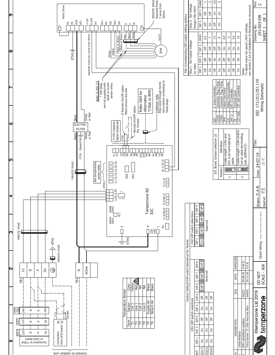
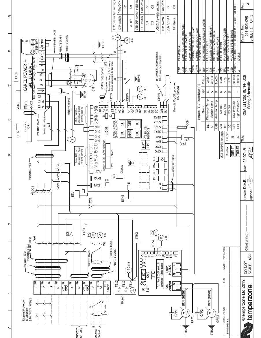
The document contains comprehensive wiring schematics for both the indoor and outdoor units. Technicians must refer to these diagrams for correct connection of the indoor-outdoor link, power supply, and control wiring.
DIP Switch Configuration
The system requires specific DIP switch settings for commissioning. Refer to the tables provided in the wiring diagrams for:
- Indoor Unit: DIP switch selections for output voltage and range settings.
- Outdoor Unit: DIP switch settings for the UC8 controller and VSD (Variable Speed Drive).
Always ensure the power is isolated before adjusting DIP switches or performing wiring connections.
Practical help
Common problems
Incorrect fan speed settings
Adjust the DIP switches on the indoor unit controller according to the 'Site commissioning DIP switch setting options' table.
Communication or control issues
Verify wiring connections against the provided schematics, ensuring ferrite cores are installed as instructed.
Before use
- Verify power supply is 3 phase 400V AC 50Hz.
- Check that refrigerant charge is correct for the line length (precharge for 15m).
- Ensure all minimum clearance distances are maintained around the units.
- Confirm pipe sizes (19mm suction, 9.5mm liquid) are correct.
- Verify DIP switch settings match the required system configuration.
Show more Show less
Specs in practice
- Cooling Capacity
- The total cooling output of the system, ranging from 9.4 to 25.3 kW.
- Max Line Length
- The maximum allowable distance between indoor and outdoor units is 60 meters.
Images and diagrams
- Indoor Unit Wiring: Shows connections for T/Stat, Zone Board, and DIP switch settings.
- Outdoor Unit Wiring: Shows connections for power, sensors, and UC8 controller settings.
- Dimensions: Provides mounting centers and clearance requirements for installation.
Model compatibility
- Compatible with SAT-3 Room temperature controller.
- Compatible with TZT-100 Room temperature controller.
- Requires 3 phase 400V power supply.

Manual page author
Emily Carter
User documentation editor