Electronics / Cables & Adapters
Corning FREEDM LST Loose Tube Cable Specification Sheet
Technical specifications and installation guidelines for the Corning FREEDM LST Loose Tube, Gel-Free Plenum Cable (12 Fiber, 50 µm OM3). Includes mechanical, optical, and environmental data.
Table of contents
Quick guide from the manual
This document provides the technical specifications and construction details for the Corning FREEDM LST Loose Tube, Gel-Free Plenum Cable (Part Number: 012TSP-T4180D20). This cable is designed for indoor/outdoor use, featuring a 12-fiber count and 50 µm OM3 multimode fiber. It is flame-retardant, UV-resistant, and requires no grounding or bonding due to its all-dielectric construction.
Product Overview
The FREEDM LST cable utilizes a loose tube design with gel-free waterblocking technology, which simplifies cable preparation and installation. The cable is plenum-rated (OFNP) and meets NEC Article 770 requirements, making it suitable for interbuilding and intrabuilding backbones in aerial, duct, riser, or plenum applications.
Environmental Conditions
Adhering to temperature limits is critical for maintaining cable integrity:
- Installation Temperature: 0 °C to 60 °C (32 °F to 140 °F)
- Operation Temperature: -40 °C to 70 °C (-40 °F to 158 °F)
- Storage Temperature: -40 °C to 70 °C (-40 °F to 158 °F)
Mechanical Specifications
Proper handling during installation is required to avoid damage to the fibers:
- Max. Tensile Strength (Long-Term): 400 N (89.92 lbf)
- Max. Tensile Strength (Short-Term): 1350 N (303.49 lbf)
- Min. Bend Radius (Installation): 111 mm (4.37 in)
- Min. Bend Radius (Operation): 74 mm (2.91 in)
- Nominal Outer Diameter: 7.4 mm (0.29 in)
Optical Characteristics
The cable is optimized for high-speed data transmission:
- Fiber Type: Multimode (OM3)
- Fiber Core Diameter: 50 µm
- Wavelengths: 850 nm / 1300 nm
- Maximum Attenuation: 3.0 dB/km / 1.0 dB/km
- Serial 10 Gigabit Ethernet: 300 MHz*km
Cable Design
The cable construction includes:
- Fiber Count: 12
- Buffer Tube Color: Aqua
- Number of Ripcords: 2
- Outer Jacket Material: Flame-Retardant, UV-Resistant
- Tensile Strength Elements: Dielectric strength members
Manufacturer information
Corning Optical Communications
Practical help
Common problems
Signal loss due to tight bends
Ensure the cable is not bent tighter than 111 mm during installation or 74 mm during operation.
Installation failure due to temperature
Do not install the cable if the ambient temperature is below 0°C or above 60°C.
Before use
- Verify the part number is 012TSP-T4180D20.
- Confirm the application environment is suitable for plenum-rated cables.
- Ensure the installation path allows for the minimum bend radius of 111 mm.
- Check that the pulling force does not exceed the short-term tensile strength of 1350 N.
Specs in practice
- Max. Tensile Strength (Short-Term)
- The maximum pulling force that can be applied to the cable during installation.
- Min. Bend Radius (Installation)
- The tightest curve the cable can handle while being pulled without damaging the fibers.
Images and diagrams
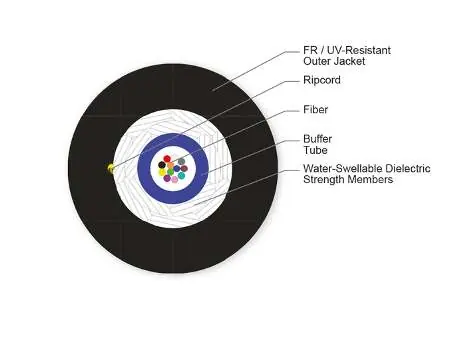
- The cross-section diagram illustrates the internal structure: the FR/UV-resistant outer jacket, ripcord, fiber, buffer tube, and water-swellable dielectric strength members.
Model compatibility
- Compatible with standard 50 µm OM3 multimode fiber systems.
- Meets NEC Article 770, OFNP, and FT-6 standards.

Manual page author
Michael Turner
Technical manual editor
Reviews PDF manuals for structure, safety notes, and practical product details so readers can find the right information quickly.