Electronics / Cables & Adapters
Corning MIC Tight-Buffered Cable 024E88-33131-29 Specification
Technical specification and installation guidelines for the Corning MIC Tight-Buffered Cable (024E88-33131-29). Includes environmental ratings, mechanical specifications, and cable design details.
Table of contents
Manual images
Click an image to enlargeQuick guide from the manual
This document provides the technical specifications for the Corning MIC Tight-Buffered Cable (Part Number: 024E88-33131-29). This cable is designed for use in plenum, riser, and general-purpose environments for intrabuilding backbone and horizontal installations. It features an all-dielectric construction, meaning no grounding or bonding is required.
Product Description
The MIC plenum cable utilizes 900 µm buffered fibers to facilitate easy and consistent stripping during termination. The fibers are protected by dielectric strength members and a flame-retardant outer jacket. The cable meets the application requirements of the National Electrical Code (NEC) Article 770 and is OFNP and FT-6 listed.
Environmental Conditions
Ensure the cable is handled and stored within the following temperature ranges:
- Installation: 0 °C to 60 °C (32 °F to 140 °F)
- Operation: 0 °C to 70 °C (32 °F to 158 °F)
- Storage: -40 °C to 70 °C (-40 °F to 158 °F)
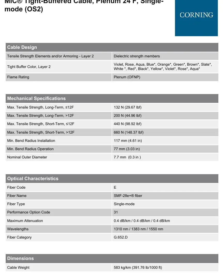
Mechanical Specifications
Adhere to the following mechanical limits to ensure cable integrity:
- Max. Tensile Strength (Long-Term, ≤12F): 132 N (29.67 lbf)
- Max. Tensile Strength (Long-Term, >12F): 200 N (44.96 lbf)
- Max. Tensile Strength (Short-Term, ≤12F): 440 N (98.92 lbf)
- Max. Tensile Strength (Short-Term, >12F): 660 N (148.37 lbf)
- Min. Bend Radius (Installation): 117 mm (4.61 in)
- Min. Bend Radius (Operation): 77 mm (3.03 in)
- Nominal Outer Diameter: 7.7 mm (0.3 in)
Optical Characteristics
The cable utilizes SMF-28e+ fiber (Single-mode, G.652.D category). The maximum attenuation is 0.4 dB/km across the supported wavelengths of 1310 nm, 1383 nm, and 1550 nm.
Cable Design
The cable features a central yarn element, 24 fibers, and a yellow flame-retardant outer jacket. The tight buffer colors include Violet, Rose, Aqua, Blue, Orange, Green, Brown, Slate, White, Red, Black, and Yellow.
Standards and Compliance
This product is RoHS compliant (2011/65/EU) and meets the following standards:
- National Electrical Code (NEC) OFNP
- NFPA 262
- CSA FT-6
- ICEA S-83-596
Manufacturer information
Corning Optical Communications
Practical help
Common problems
Exceeding bend radius during installation
Ensure the cable is not bent tighter than 117 mm during installation or 77 mm during operation.
Temperature limit violation
Ensure installation environment is between 0 °C and 60 °C. Do not install in environments outside this range.
Before use
- Verify part number 024E88-33131-29 matches project requirements.
- Confirm the environment is suitable for Plenum (OFNP) rated cable.
- Ensure installation temperature is within 0 °C to 60 °C.
- Check that the cable path allows for the minimum bend radius of 117 mm.
Specs in practice
- Flame Rating
- Plenum (OFNP) rated, suitable for use in plenum spaces.
- Fiber Category
- Single-mode (OS2) G.652.D, optimized for long-distance transmission.
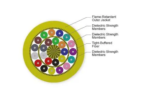
Images and diagrams
- The cross-section diagram illustrates the internal structure, showing the arrangement of 24 fibers, dielectric strength members, and the flame-retardant outer jacket.
Model compatibility
- Compatible with NEC Article 770 requirements.
- Suitable for plenum, riser, and general-purpose intrabuilding installations.

Manual page author
Michael Turner
Technical manual editor
Reviews PDF manuals for structure, safety notes, and practical product details so readers can find the right information quickly.