Computers / Computer Cases
Installation Guide for Corsair Carbide Series 200R Mid-Tower Case
A comprehensive installation guide for the Corsair Carbide Series 200R mid-tower case. This manual covers component installation, hardware compatibility, and cable management.
Quick answers from the manual
Quick answer
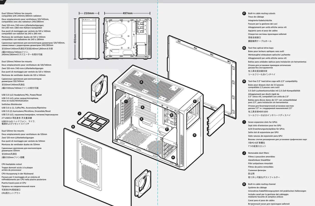
- The Corsair Carbide Series 200R is a mid-tower case designed for easy component installation. It features tool-free drive bays, cable routing cutouts, and supports high-performance components like long GPUs and large CPU coolers. p. 2
Key actions
- Install motherboard I/O shield p. 6
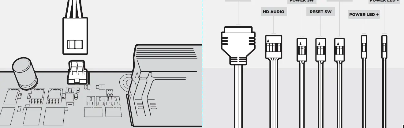
- Connect front I/O cables p. 9
Technical specifications
| Parameter | Value | Meaning | Pages |
|---|---|---|---|
| Max GPU length (top) | 430mm | Maximum length for graphics cards in top slots | p. 4 |
| Max GPU length (lower) | 320mm | Maximum length for graphics cards in lower slots | p. 4 |
| Max CPU cooler height | 160mm | Maximum height for CPU cooling systems | p. 4 |
Show 1 more answers Show less
Where to find it in the PDF
- Installation Guide p. 1
- Features p. 2, 3
- Package Contents p. 4
- Installation Steps p. 6, 7, 8, 9
Table of contents
Manual images
Click an image to enlargeQuick guide from the manual
The Corsair Carbide Series 200R is a mid-tower case designed for easy component installation. It features tool-free drive bays, cable routing cutouts, and supports high-performance components like long GPUs and large CPU coolers. This guide provides the necessary steps to assemble your system.
Package contents
Ensure you have the following hardware before starting:
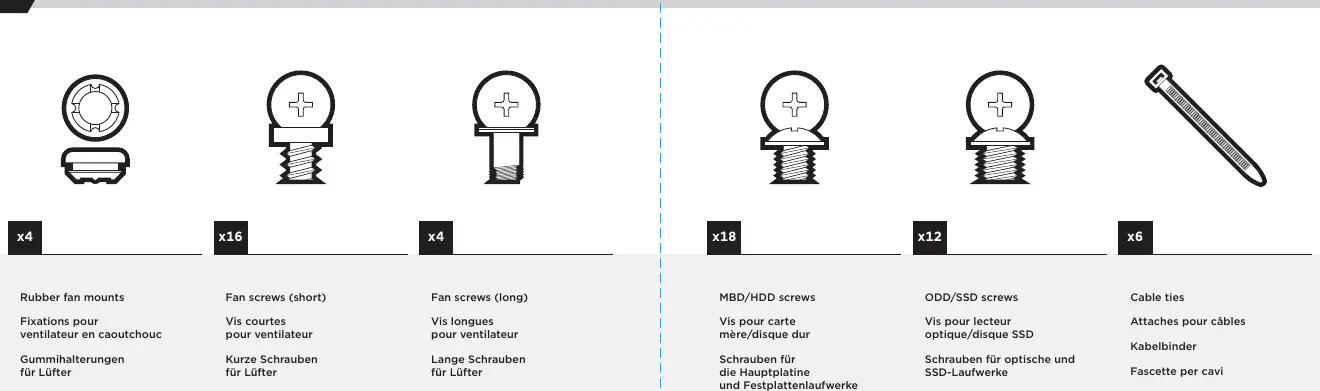
- Rubber fan mounts (x4)
- Fan screws (short) (x16)
- Fan screws (long) (x4)
- MBD/HDD screws (x18)
- ODD/SSD screws (x12)
- Cable ties (x6)
Technical specifications
- Maximum GPU length (top slots): 430mm
- Maximum GPU length (lower slots): 320mm
- Maximum CPU cooler height: 160mm
Installation steps
1. Removing the side panels
Unscrew the thumbscrews and remove them, then pull the side panels outward.
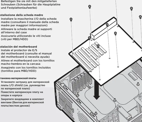
2. Installing the motherboard
Install your motherboard’s I/O shield (refer to your motherboard manual). Align the motherboard with the standoffs in the case and secure it using the included MBD/HDD screws.
3. Installing the power supply (PSU)
Place the PSU on the bottom of the case. Align the holes and secure it with screws. Note: The PSU can be installed with the fan facing either up or down.
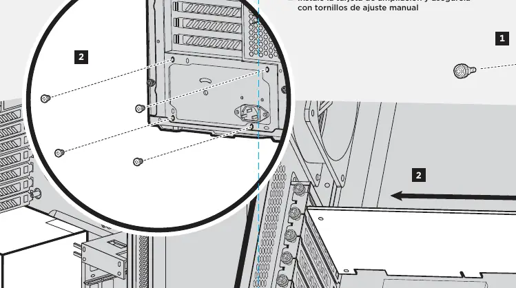
4. Installing PCI-E/PCI cards
Remove the thumbscrews and corresponding slot covers. Install the add-on card and secure it with the thumbscrew.
5. Installing 5.25" drive/devices
Remove the front panel blank for the 5.25" drive bay. Insert the drive, pulling back the tool-free latch until it aligns with the mounting holes on your device, then release.
6. Installing 3.5" HDD / 2.5" SSD
Place the drive into the tool-free cage until you feel it secure. To remove the drive, pull the tab to release.
7. Connecting case fans
Attach case fan cables to motherboard headers. Consult your motherboard manual for fan header locations.
8. Installing front I/O connectors
Connect the front I/O cables (USB 3.0, HD Audio, Power/Reset switches, LEDs) to the motherboard. Consult your motherboard manual for front panel header locations and pin-outs.
Manufacturer information
Corsair Memory, Inc.
Practical help
Common problems
Difficulty installing motherboard
Ensure the I/O shield is installed first and the motherboard is aligned with the standoffs.
PSU installation orientation
The PSU can be installed with the fan facing either up or down.
Removing drives
For 3.5"/2.5" drives, pull the tab on the tool-free cage to release.
Before use
- Verify all screws and standoffs are present
- Have a screwdriver ready for motherboard installation
- Check motherboard manual for I/O shield and header locations
Show more Show less
Specs in practice
- Max GPU length (top slots)
- 430mm
- Max GPU length (lower slots)
- 320mm
- Max CPU cooler height
- 160mm
Images and diagrams
- The manual provides diagrams for screw types, motherboard installation, PSU placement, and front I/O connector pinouts.
Model compatibility
- Supports 240mm/280mm radiators
- Tool-free installation for SSDs, HDDs, and optical drives

Manual page author
David Miller
Documentation analyst