Computers / Computer Cases
User Manual for Corsair iCUE 2000D RGB Airflow ITX Tower Case
Quick guide for the Corsair iCUE 2000D RGB Airflow ITX Tower Case. Includes installation steps for motherboard, PSU, SSD, fans, and front I/O connection details.
Quick answers from the manual
Quick answer
- This manual provides assembly instructions for the Corsair iCUE 2000D RGB Airflow ITX Tower Case, including component installation, cable routing, and I/O connection diagrams. p. 1, 12
Key actions
- Remove side panels p. 4
- Install motherboard p. 6
- Install PSU p. 8
Problems and fixes
Damaged case or fan
Request RMA at support.corsair.com
p. 12Show 2 more answers Show less
Technical specifications
| Parameter | Value | Meaning | Pages |
|---|---|---|---|
| Max GPU Length | 320mm | Maximum supported graphics card length | p. 2 |
| Max PSU Length | 130mm | Maximum supported power supply length | p. 2 |
Where to find it in the PDF
- Specifications p. 2
- Installation p. 4, 11
- I/O Connections p. 12
Table of contents
Quick guide from the manual
This document provides assembly and installation instructions for the Corsair iCUE 2000D RGB Airflow ITX Tower Case. It covers component compatibility, accessory identification, and step-by-step installation procedures for the motherboard, power supply, storage, and cooling fans.
Case Specifications
Before beginning assembly, ensure your components fit within the following limits:
- Maximum GPU length: 320mm
- Maximum CPU height: 90mm
- Maximum PSU length: 130mm
- Fan locations: Front (3x 120mm), Top (1x 120mm slim), Rear (2x 120mm), Side (3x 120mm / 2x 140mm)
- Radiator compatibility: Side (360mm / 280mm), Rear (240mm)
Accessory Kit Contents
Verify you have the following components before starting:
- Fan screws (short)
- MBD / HDD screws
- SSD screws
- Motherboard standoffs
- Cable ties
Installation Procedures
Removing Panels
The front, top, and side panels are removable to allow access to the interior. Ensure you release the locking mechanisms before attempting to remove the panels.
Fan and Radiator Bracket
The side fan/radiator bracket can be removed to facilitate the installation of cooling components. Follow the numbered steps in the manual to detach and reattach the bracket securely.
Motherboard Installation
This case is designed for Mini-ITX motherboards. Align the motherboard with the I/O area and secure it using the provided standoffs and screws.
PSU Installation
The PSU shroud may need to be removed depending on your power supply type (SFX or SFX-L). Ensure the PSU is oriented correctly for proper airflow and cable routing.
SSD Installation
Use the removable SSD trays to mount your drives. Secure the drives to the trays and then attach the trays to the designated mounting points within the case.
Front I/O Connections
Connect the front panel cables to your motherboard headers. The diagram in the manual identifies the following connectors:
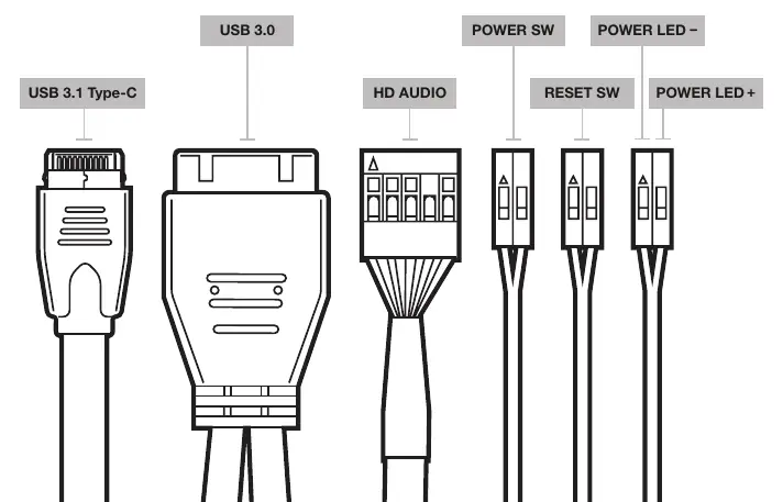
- USB 3.1 Type-C
- USB 3.0
- HD Audio
- Power Switch
- Reset Switch
- Power LED (+/-)
Note: Polarity matters for the LED headers, but not for the power and reset headers.
Manufacturer information
Corsair Memory, Inc.
Practical help
Common problems
Damaged case or fan not working
Contact support.corsair.com to request an RMA for replacement parts.
Polarity of I/O headers
Polarity does not matter for power and reset headers, but it does matter for LED headers.
Before use
- Verify all screws and standoffs are present from the accessory kit.
- Ensure your motherboard is Mini-ITX format.
- Check PSU length (max 130mm).
- Check GPU length (max 320mm).
Show more Show less
Specs in practice
- Maximum GPU length
- 320mm
- Maximum CPU height
- 90mm
- Maximum PSU length
- 130mm
Images and diagrams
- Exploded view of the case shows locations of panels, fans, and SSD trays.
- Front I/O diagram identifies USB 3.1 Type-C, USB 3.0, HD Audio, Power/Reset switches, and LED headers.
Model compatibility
- Supports Mini-ITX motherboards only.
- PSU shroud removal is required for certain PSU types.
- Radiator support varies by location (Side: 360mm/280mm, Rear: 240mm).

Manual page author
David Miller
Documentation analyst