Electronics / Networking
D-Link DGS-1016D/DGS-1024D Unmanaged Switch Quick Start Guide
Quick start guide for D-Link DGS-1016D and DGS-1024D unmanaged switches. Includes hardware connection diagrams, LED indicator explanations, and setup instructions.
Table of contents
Quick guide from the manual
This document provides the essential steps to install and connect your D-Link DGS-1016D or DGS-1024D unmanaged switch. It is designed to help you get your network hardware up and running quickly.
Hardware Connection
To set up the switch, follow these steps:
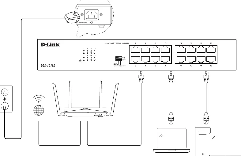
- Power Connection: Plug the power cord into the power port on the back of the switch. Use the included power cord retainer to secure the cable and prevent accidental disconnection.
- Network Connection: Connect your network devices (such as computers, laptops, or routers) to the numbered RJ45 ports on the front panel using standard Ethernet cables.
LED Indicators
The front panel features LED indicators to help you monitor the status of your connections:
- Link/Act: Indicates the connection status and data activity on the port.
- 1000M: Indicates that the connected device is operating at Gigabit Ethernet speeds.
- 10/100M: Indicates that the connected device is operating at Fast Ethernet speeds.
Switch Settings
The front panel includes a DIP switch configuration area for specific network management features:
- EEE: Energy Efficient Ethernet settings.
- Flow Control: Manages data flow to prevent buffer overflow.
- Port Isolation & Storm Control: Advanced features for network security and traffic management.
Support Resources
For further assistance, documentation, and warranty information, please visit the official D-Link support website at https://www.dlink.com/en/support or the resources page at https://www.dlink.com/resources/business. Warranty details can be found at http://warranty.dlink.com.
Official resources from the manual
Manufacturer information
D-Link Corporation
Practical help
Common problems
Device not connecting to the network
Ensure the Ethernet cable is securely plugged into both the switch port and the device. Verify that the Link/Act LED is lit.
Switch loses power
Check that the power cord is fully inserted into the switch and the power outlet. Ensure the power cord retainer is properly installed to prevent the cable from slipping out.
Before use
- Verify that you have a stable power source.
- Ensure you have sufficient Ethernet cables (Cat5e or better recommended).
- Place the switch on a flat, stable surface with adequate ventilation.
- Check that the power cord retainer is available for installation.
Specs in practice
- Link/Act LED
- Solid light indicates a valid link; blinking light indicates data transmission/activity.
Images and diagrams
- The connection diagram illustrates the power cord insertion and the use of the retainer clip on the rear panel.
- The diagram shows the correct method for connecting multiple devices (PC, laptop, router) to the front-facing RJ45 ports.
Model compatibility
- The switch is compatible with standard Ethernet devices.
- Ensure cables used meet the requirements for the desired network speed (Cat5e or Cat6 for Gigabit).

Manual page author
Michael Turner
Technical manual editor
Reviews PDF manuals for structure, safety notes, and practical product details so readers can find the right information quickly.