Home / Security
Dahua 16/24-Port Managed Desktop PoE Switch User Guide
Quick start guide for the Dahua 16/24-port managed desktop PoE switch. Includes installation, wiring, web configuration, and cybersecurity recommendations.
Table of contents
Manual images
Click an image to enlargeQuick Guide
This guide provides essential information for setting up and operating the Dahua 16/24-port managed desktop PoE switch. Key steps include rack mounting, proper grounding, connecting power and network cables, and accessing the web management interface.
- Default IP: 192.168.1.110
- Default Username: admin
- Password: No initial password (set during first login).
- Reset: Hold the Reset button for 5 seconds to restore factory settings.
Device Overview
The device is a layer-2 commercial switch designed for video stream transmission. It features a full-metal design for heat dissipation and supports various work modes via DIP switches. It is suitable for homes, offices, and server farms.
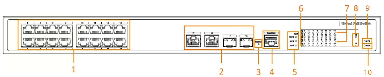
- PoE Support: Complies with IEEE802.3af/at standards. Red ports support Hi-PoE and IEEE802.3bt; orange ports support Hi-PoE.
- Extend Mode: Allows PoE transmission up to 250m at 10 Mbps.
- PoE Watchdog: Real-time detection of terminal device status.
Installation
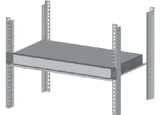
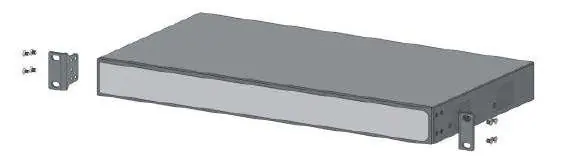
The device supports rack mounting. Attach the mounting brackets to the side panels using the provided screws, then secure the device to the rack.
- Ensure the device is installed on a solid, flat surface.
- Maintain at least 10 cm of clearance on the sides and top for heat dissipation.
- Do not block the ventilator.
Wiring
Proper wiring is critical for device safety and performance.
- Grounding: Always connect the ground terminal to a ground bar to protect against lightning and interference.
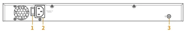
- Power: Connect the power cord to the rear power port (100–240 VAC). Ensure the device is grounded before powering on.
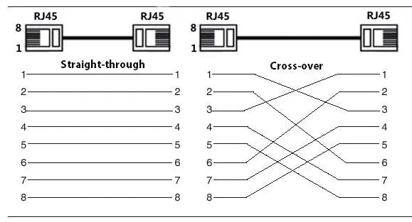
- Ethernet: Use standard RJ-45 cables. The device supports MDI/MDI-X self-recognition.
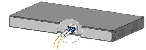
- SFP Module: Install SFP modules carefully. Do not touch the gold fingers. Unplug optical fibers before inserting the module.
- PoE Connection: Connect PoE-enabled terminal devices directly to the PoE ports. Maximum distance is 100m (or 250m in Extend mode).
Quick Operation
Access the device management interface via a web browser.
- Connect your computer to the switch.
- Enter 192.168.1.110 in your browser.
- Log in with the username 'admin' and set your password during the first initialization.
Cybersecurity Recommendations
To ensure network security, follow these mandatory actions:
- Use Strong Passwords: Minimum 8 characters, including mixed character types.
- Update Firmware: Keep firmware up-to-date to receive security patches.
- Physical Protection: Restrict physical access to the device.
- Network Security: Disable unnecessary services (SNMP, SMTP, etc.), enable HTTPS, and use IP/MAC address filtering.
Manufacturer information
Zhejiang Dahua Technology Co., Ltd.
Practical help
Common problems
Device does not power on
Check the power cable connection and ensure the rear power switch is turned on.
PoE device not receiving power
Ensure the device is connected to a PoE-capable port and that the total power budget is not exceeded.
Cannot access web interface
Verify your computer's IP address is in the same subnet as the switch (192.168.1.x) and check cable connections.
Forgotten password
Press and hold the Reset button on the front panel for more than 5 seconds to restore factory settings.
Before use
- Ensure the device is securely grounded.
- Verify the power supply voltage is between 100–240 VAC.
- Check that the installation area is well-ventilated with 10cm clearance.
- Ensure the device is placed on a solid, flat surface.
- Confirm all cables are properly connected before powering on.
Specs in practice
- PoE Watchdog
- A feature that automatically detects the status of connected terminal devices.
- Layer-2 Switch
- A network device that operates at the data link layer to manage local network traffic.
Images and diagrams
- Front Panel: Displays PoE ports, uplink ports, reset button, console port, and various status indicators.
- Rear Panel: Shows the power switch, power input port, and the ground terminal.
- Wiring: Illustrates the correct grounding procedure, Ethernet pinout (568B standard), and SFP module installation.
Model compatibility
- Supports IEEE802.3af and IEEE802.3at standards.
- Red ports support Hi-PoE and IEEE802.3bt standards.
- Orange ports support Hi-PoE standard.

Manual page author
Emily Carter
User documentation editor
Prepares concise manual descriptions and highlights the most useful setup, operation, and maintenance information for readers.