Electronics / Networking
Dahua 16/24-Port Unmanaged Desktop Switch User Manual
Quick start guide for the Dahua 16/24-Port Unmanaged Desktop Switch. Learn about installation, wiring, PoE settings, DIP switch modes, and network security recommendations.
Table of contents
Manual images
Click an image to enlargeQuick Guide from the Manual
This document provides installation and operation instructions for the Dahua 16/24-Port Unmanaged Desktop Switch. The device is designed for commercial use, featuring a full-metal shell for heat dissipation and support for various work modes via DIP switches. It is suitable for homes, offices, and server farms.
Safety Instructions
Before using the device, observe the following safety requirements:
- Installation: Ensure the device is grounded using a copper wire (2.5 mm2) with ground resistance no more than 4 Ω. Maintain at least 10 cm of clearance on sides and top for heat dissipation.
- Power: Use an adapter provided by the manufacturer. Ensure the power supply is connected to a socket with protective earthing. Do not connect the power adapter while it is powered on.
- Environment: Operate within -10 °C to +55 °C. Keep away from sunlight, heat sources, dampness, dust, and soot.
- Maintenance: Power off the device before performing any maintenance.
Port and Indicator
The front panel features various indicators and ports:
- Ethernet/Uplink Port Indicators: Solid light indicates a link; flashing indicates data transmission.
- Power Indicator: Solid light indicates the device is powered on.
- PSE Port Status Indicator: Indicates power output status (On if >=76% of rated output).
- DIP Switch: Allows configuration of PoE Watchdog, Extend Mode (up to 250m at 10 Mbps), VIP Port (QoS), and Port Isolation.
The rear panel contains the power port (100–240 VAC) and the ground terminal.
Installation
The switch supports rack mounting:
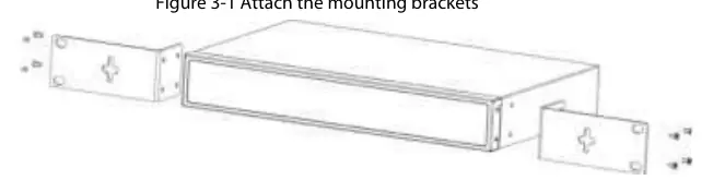
- Attach the mounting brackets to the side panels of the switch using the provided screws.
- Secure the switch to the rack using the appropriate screws.
Wiring
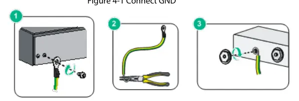
- Grounding: Remove the ground screw, pass it through the OT terminal of the ground cable, and fasten it to the device. Connect the other end to a ground bar.
- Power: Connect the power cord to the device and then to an external power socket.
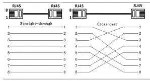
- Ethernet: Use standard RJ-45 cables. The ports support auto-MDI/MDI-X.
- PoE: Connect PoE-compatible devices directly to the PoE ports. For non-PoE devices, use an isolated power supply.
Cybersecurity Recommendations
To secure your network, follow these mandatory actions:
- Passwords: Use strong passwords (at least 8 characters, mixed types, no continuous/overlapped characters).
- Firmware: Keep firmware and client software updated.
- Network Security: Enable account lock, change default ports (1024–65535), enable HTTPS, and disable unnecessary services like SNMP, SMTP, or UPnP if not required.
Practical help
Common problems
Device not powering on
Check the power cord connection and ensure the external power socket is active.
PoE device not working
Verify the device is PoE compatible and check that the cable length does not exceed 100m (or 250m in Extend Mode).
Network connection failure
Check the Ethernet cable integrity and ensure the port indicator is lit.
Before use
- Ensure the device is grounded with a 2.5 mm2 copper wire.
- Verify the power supply is 100–240 VAC.
- Ensure at least 10 cm of clearance around the device for ventilation.
- Check that the operating environment is between -10 °C and +55 °C.
- Ensure the power plug is easily accessible.
Specs in practice
- PoE Watchdog
- Automatically restarts the terminal device if a crash is detected.
- Port Isolation
- Isolates downlink ports to prevent communication between them.
Images and diagrams
- Front Panel: Shows Ethernet, Uplink, and PoE status indicators.
- Rear Panel: Shows power input and grounding terminal.
- Wiring: Illustrates proper grounding and RJ-45 pinout (568B standard).
Model compatibility
- Supports IEEE802.3af and IEEE802.3at standards.
- Orange ports support Hi-PoE.

Manual page author
Michael Turner
Technical manual editor
Reviews PDF manuals for structure, safety notes, and practical product details so readers can find the right information quickly.