Electronics / Networking
User Manual for Digitus 16/24FE PoE Switch
Quick guide for the Digitus 16/24FE (PoE) + 2G Combo PoE Switch. Includes installation instructions, LED indicator explanations, DIP switch modes (VLAN, CCTV), and technical specifications.
Table of contents
Manual images
Click an image to enlargeQuick Guide
This manual covers the operation and installation of the Digitus 16/24FE (PoE) + 2G Combo PoE Switch. This device is an unmanaged Gigabit Uplink switch designed to provide power and data to IEEE 802.3af/at compliant devices such as IP cameras, access points, and IP phones over a single Ethernet cable.
Package Contents
- PoE Switch x 1
- Manual x 1
- Power Cord x 1
- Accessories (Mounting Ears x2, Rubber Feet x4, screw x8)
Hardware Description
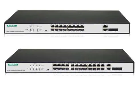
The front panel features 16 or 24 10/100Mbps PoE RJ45 ports and 2 Gigabit Combo ports. LED indicators provide real-time status of power, link/activity, speed, and PoE status. The rear panel contains the AC power inlet and a grounding column.
Installation
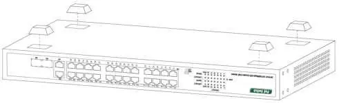
Desktop Installation: Attach the provided rubber feet to the bottom corners of the switch to prevent vibration and ensure adequate ventilation space.
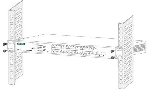
Rack-mountable Installation: Attach the mounting brackets to the side panels of the switch using the included screws. Secure the switch to a standard EIA-19 inch equipment rack using the screws provided with your rack.
Safety Precautions: Ensure the operating voltage matches the label on the switch (100-240V). Do not place the switch near water or in damp areas. Keep ventilation vents free of obstruction.
Operation and DIP Switch Settings
The switch includes a DIP switch on the left panel to change operating modes. Note that the switch must be restarted manually after changing the mode for the configuration to take effect.
- Default: Standard communication between all ports.
- VLAN: Isolates ports 1-24 from each other, but allows them to connect to the 25T/S-26T/S ports. This helps stop broadcast storms and increases forwarding rates.
- CCTV: Extends PoE transmission distance up to 250m, suitable for fixed devices like IP cameras.
Specifications
The switch supports IEEE 802.3af/at standards. The PoE power budget is 370W for the 16FE model and 250W for the 24FE model. Operating temperature is 0°C to 40°C. The device features a store-and-forward transfer mode and supports 16K MAC addresses with automatic learning and aging.
Practical help
Common problems
PWR LED is off
Check that the power cord is securely connected to both the device and the power outlet.
PoE device not receiving power
Ensure the device is IEEE 802.3af/at compliant and the cable length does not exceed 100m.
PoE LED is blinking
This indicates an abnormal power supply to the port; check for short circuits or incompatible devices.
Before use
- Verify all package contents are present.
- Ensure the installation surface is stable and allows for proper ventilation.
- Check that the power source voltage matches the switch requirements (100-240V).
- Ensure you have the correct mounting hardware for your installation type (desktop or rack).
Images and diagrams
- Front Panel: Displays port layout, status LEDs, and combo ports.
- Desktop Installation: Illustrates the placement of rubber feet on the bottom of the chassis.
- Rack Installation: Shows how to attach mounting brackets to the sides of the switch.
Model compatibility
- Supports IEEE 802.3af/at compliant Powered Devices (PD).
- Requires manual restart after changing DIP switch settings.
- Class A product; may cause radio interference in home environments.

Manual page author
David Miller
Documentation analyst
Organizes user manual content into clear summaries, with attention to model details, product context, and everyday usability.