Hvac / Thermostats Controls
Installation Guide for Danfoss CAS 178, CAS 180, CAS 181 Thermostats
A comprehensive installation and configuration guide for Danfoss CAS 178, CAS 180, and CAS 181 thermostats. Includes technical specifications, wiring diagrams, and instructions for adjusting temperature ranges and differentials.
Table of contents
Quick guide from the manual
This document provides installation and setup instructions for the Danfoss CAS 178, CAS 180, and CAS 181 thermostats. These devices are designed for temperature control applications. Users must ensure that the ambient temperature (T1) and sensor temperature (T2) remain within the specified limits for each model to prevent damage and ensure accurate operation. The installation involves mounting the unit, connecting the wiring to terminals 1, 2, and 4, and adjusting the range and differential settings via the internal screws.
Technical specifications
The operating limits vary by model. Ensure your application matches these requirements:
- CAS 178: T2 max 130°C, Differential 2.0°C.
- CAS 180: T2 max 220°C, T1 min -25°C, T1 max 70°C, Differential 2.5°C.
- CAS 181: T2 max 250°C, Differential 2.5°C.
The device is available in different lengths (75mm, 110mm, 160mm) and materials (Brass or Steel 18/8).
Installation and wiring
The thermostat housing should be mounted securely. Wiring is performed using terminals 1, 2, and 4. Refer to the wiring diagrams provided in the manual to ensure the correct configuration for your specific control circuit. Ensure all electrical connections are tight and compliant with local safety standards.
Adjustment procedures
The thermostat features adjustable settings for the temperature range and the switching differential:
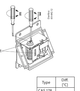
- Range Adjustment: Use the designated adjustment screw to set the desired temperature range.
- Differential Adjustment: Use the differential screw to set the switching gap. The differential is fixed at 2.0°C for CAS 178 and 2.5°C for CAS 180 and CAS 181.
Follow the visual indicators on the device to increase or decrease settings as required by your application.
Manufacturer information
Danfoss A/S
Practical help
Common problems
Thermostat not switching at the correct temperature
Verify that the range and differential screws are set correctly. Ensure the sensor is not exceeding the T2 max temperature limit.
Ambient temperature issues
For CAS 180, ensure the ambient temperature (T1) is between -25°C and 70°C.
Before use
- Identify the specific model (CAS 178, 180, or 181).
- Verify the maximum sensor temperature (T2) for your model.
- Check that the ambient temperature (T1) is within the allowed range.
- Ensure the correct wiring configuration for terminals 1, 2, and 4.
- Confirm the required length and material (Brass/Steel) for your installation.
Images and diagrams
- Wiring Diagram: Illustrates the connection points for terminals 1, 2, and 4.
- Adjustment Diagram: Shows the location of the range and differential adjustment screws.
Model compatibility
- Ensure the thermostat material (Brass or Steel 18/8) is compatible with the medium being measured.

Manual page author
Emily Carter
User documentation editor
Prepares concise manual descriptions and highlights the most useful setup, operation, and maintenance information for readers.