Power / Batteries & Chargers
Design Guide for Danfoss VLT® Advanced Harmonic Filter AHF 005/AHF 010
Comprehensive design and installation guide for Danfoss VLT® Advanced Harmonic Filter AHF 005/AHF 010. Includes mechanical mounting, electrical wiring, programming parameters, and technical specifications.
Table of contents
Manual images
Click an image to enlargeImportant Information from the Manual
This design guide provides essential information for the installation, operation, and programming of the Danfoss VLT® Advanced Harmonic Filter (AHF) 005 and AHF 010. These filters are designed to mitigate harmonic distortion in electrical systems using Danfoss frequency converters. Always ensure that installation, start-up, and maintenance are performed by qualified personnel.
Safety Precautions
- High Voltage: Filters contain high voltage when connected to AC mains. Never work on a filter in operation.
- Discharge Time: Capacitors can remain charged even when the filter is not powered. Wait the specified time on the nameplate before performing service.
- Hot Surface: Filter surfaces become hot during operation. Do not touch.
- Overtemperature: Use temperature switches to prevent damage to filter chokes. Perform an immediate stop or controlled ramp down within 30 seconds if overheating occurs.
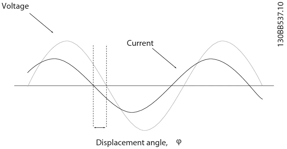
Operating Principle
The AHF 005 and AHF 010 are passive harmonic filters. The AHF 005 provides 5% THDi performance, while the AHF 010 provides 10% THDi performance. The filters are specific to the supply frequency (50 Hz or 60 Hz). Capacitive currents are present at no-load conditions; if these are not acceptable, a capacitor disconnect should be used.
Mechanical Mounting
- Mount all filters vertically with terminals at the bottom.
- Ensure minimum 150 mm (5.91 in) clearance at the top and bottom.
- Do not mount near heat-sensitive materials or other heating elements.
- Use dedicated lifting eyes for installation. For X3-V3 to X8-V3 enclosures, use extra lifting eyes in the centerline.
- For rail-mounted installations, use a backplate to prevent false airflow.
Electrical Installation
The filter includes terminals for mains supply (X1.1–X1.3), output to frequency converter (X2.1–X2.3), and optional capacitor disconnect (X3.1–X4.3). Temperature switches (A and B) must be connected to the frequency converter to prevent damage. Ensure cables comply with local regulations and maintain proper grounding.
Programming
The manual details parameters for digital inputs and outputs to support the AHF. Key functions include:
- Overtemperature Protection: Program digital inputs to 'Coast Inverse' or 'Motor Thermal Protection' to unload the filter if an overtemperature switch is triggered.
- Capacitor Connect: Configure digital outputs to control the capacitor disconnect contactor.
- DC-link Compensation: If resonances occur in the DC link, disable dynamic DC-link compensation by setting parameter 14-51 to [0] Off.
Specifications and Spare Parts
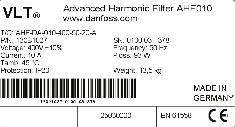
The guide includes detailed tables for power loss, acoustic noise levels, mechanical dimensions, and fuse requirements based on filter current rating and voltage class. Spare parts, including capacitor kits, fan kits, and terminal kits, are revision-specific. Always verify the revision number (01, 02, or 03) on the product label before ordering spare parts.
Manufacturer information
Danfoss A/S
Practical help
Common problems
Overtemperature switch activation
Evaluate airflow, check for blocked fan inlet/outlet, or check for a defective fan/fan control.
Voltage boost at low load
Use a capacitor disconnect to disconnect the capacitor bank at loads below 20%.
Resonances in the DC link
Disable dynamic DC-link compensation by setting parameter 14-51 to [0] Off.
Before use
- Verify the filter revision number (01, 02, or 03) on the product label.
- Ensure proper lifting equipment is used for heavy loads.
- Mount the filter vertically with terminals at the bottom.
- Ensure minimum 150 mm top and bottom clearance.
- Verify compatibility with the specific frequency converter (FC 102, 103, 202, 301/302).
Images and diagrams
- Lifting methods for internal and external fan filters.
- Connection diagram for AHF with capacitor disconnect.
- Parallel use of AHF combined with capacitor disconnect.
- Insertion loss in the frequency converter as a function of load.
Model compatibility
- Designed for Danfoss frequency converters (FC 102, 103, 202, 301/302).
- Capacitor disconnect feature does not apply to VLT® AutomationDrive FC 301.

Manual page author
Emily Carter
User documentation editor
Prepares concise manual descriptions and highlights the most useful setup, operation, and maintenance information for readers.