Hvac / Thermostats Controls
Installation Guide for Danfoss Aero RA Click Remote Thermostatic Sensor
Quick installation and configuration guide for the Danfoss Aero RA Click remote thermostatic sensor, including mounting, temperature limitation, and theft protection steps.
Table of contents
Manual images
Jump to the sectionQuick guide from the manual
This document provides essential instructions for the installation, temperature limitation, and security setup of the Danfoss Aero RA Click remote thermostatic sensor. It covers standard radiator valve mounting, BIV installation, and remote sensor positioning.
Installation
The sensor features a click-on mechanism for easy mounting:

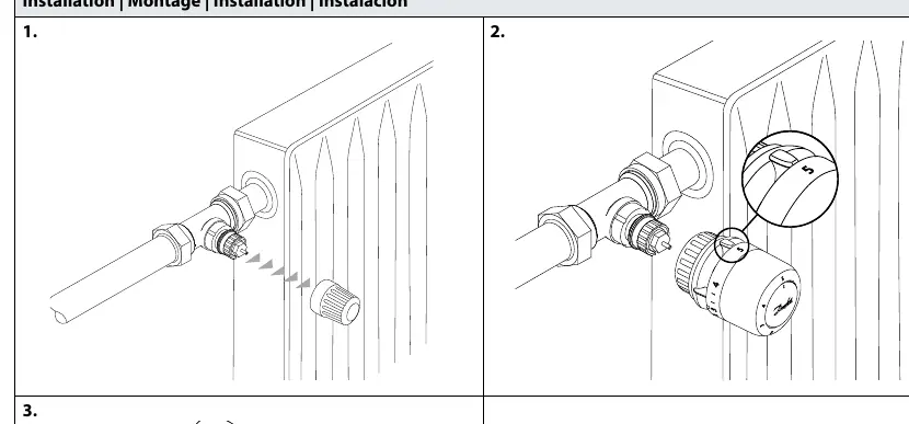
- Ensure the valve body is clean and ready.
- Align the sensor with the valve body.
- Press the sensor firmly onto the valve until you hear a distinct click, indicating it is securely locked in place.
BIV Installation
For BIV (Built-in Valve) applications, follow the same click-on procedure by aligning the sensor with the valve interface and pressing until it clicks.
Remote Sensor
The remote sensor can be positioned at a distance of 0-2 meters from the thermostatic head. Ensure the sensor is mounted using the provided bracket to maintain accurate temperature readings.
Temperature Limitation
You can restrict the temperature range to prevent overheating or excessive cooling:
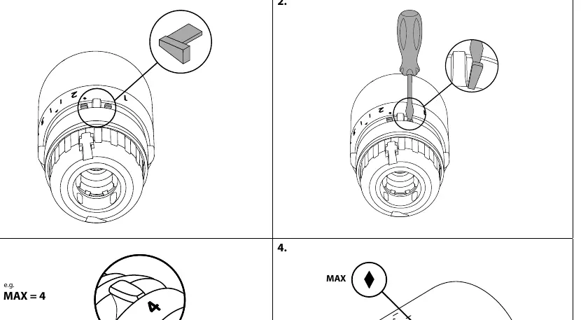
- Maximum Limitation: Use the provided limiter pin. Insert it into the desired position on the dial to cap the maximum temperature setting.
- Minimum Limitation: Similarly, insert the limiter pin into the corresponding slot to set a minimum temperature floor.
- Use a small screwdriver to adjust or remove the limiter pins as needed.
Theft Protection
To prevent unauthorized removal of the sensor:
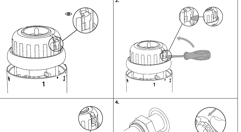
- Locate the theft protection tab on the side of the sensor.
- Insert the locking mechanism to secure the sensor to the valve.
- To remove, use a screwdriver to release the locking tab before pulling the sensor off the valve.
Manufacturer information
Danfoss A/S
Practical help
Common problems
Sensor does not lock onto the valve
Ensure the sensor is properly aligned with the valve body and press firmly until a click is heard.
Need to remove a theft-protected sensor
Use a screwdriver to gently release the locking tab on the side of the sensor before attempting to pull it off.
Before use
- Verify the valve body is compatible with the RA Click system.
- Ensure the remote sensor cable is not kinked or damaged.
- Check that the limiter pins are available if temperature restriction is required.
Specs in practice
- Remote sensor range
- The sensor can be placed up to 2 meters away from the main thermostatic head.
- Code no. 013G1246
- Limiter pin accessory for temperature adjustment.
- Code no. 013G5245
- Theft protection accessory.
Images and diagrams
- The 'click' sound indicates a successful mechanical connection between the sensor and the valve.
- The 'MAX' and 'MIN' markings on the dial indicate where the limiter pins should be inserted to restrict the temperature range.
Model compatibility
- Designed for use with Danfoss RA series valves.

Manual page author
Emily Carter
User documentation editor
Prepares concise manual descriptions and highlights the most useful setup, operation, and maintenance information for readers.