Industrial / Electrical
Installation Instructions for Danfoss VLT AutomationDrive FC 302 with Connectors
Quick installation and wiring guide for Danfoss VLT AutomationDrive FC 302 with connectors. Includes connector pinouts, safety discharge times, and cable gland specifications.
Table of contents
Manual images
Click an image to enlargeQuick guide from the manual
This document provides installation and wiring instructions for the Danfoss VLT AutomationDrive FC 302 with connectors. Important: The FC 302 with connectors is not UL approved, and ETR functionality is not guaranteed. The enclosure protection rating is IP55.
Safety Instructions
The frequency converter contains DC-link capacitors that remain charged even when the power is off. High voltage may be present. Before performing any service or repair work:
- Stop the motor.
- Disconnect AC mains and remote DC-link power supplies (including battery back-ups, UPS, and DC link connections to other frequency converters).
- Disconnect or lock the PM motor.
- Wait for the capacitors to discharge fully (minimum 4 minutes for 3x400V 0.55–7.5 kW).
- Use an appropriate voltage measuring device to verify that capacitors are fully discharged.
Connectors Overview
The frequency converter features 7 connectors plus 2 or 4 motor connectors:
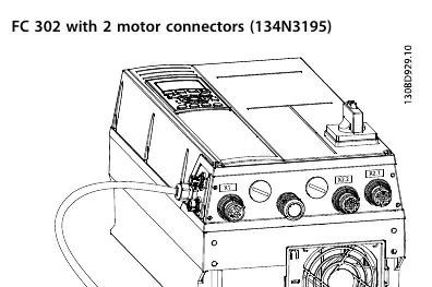
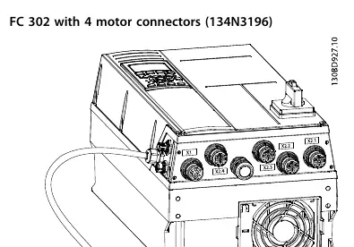
- X1: Mains in M23 (in M25) Male.
- X2.1-X2.4: Motor connection M23 Female.
- X51: PROFIBUS M12 Male.
- X52: PROFIBUS M12 Female.
- X11-X14: Phoenix I/O box connector.
Wiring Assignments
X1 Mains M23 (in M25) Male: Pins 1, 2, 3, 4 are rated for 480V AC, max 15A. Pins C and D are rated for 30V DC, max 3A. Tightening torque is 1.5–2.0 Nm.
X2 Motor Connectors M23 (in M25) Female: Pins 1, 2, 3, 4 are rated for 480V AC, max 15A. Pins C and D are rated for 30V DC, max 3A. Tightening torque is 1.5–2.0 Nm. Maximum cable length is 7.0 m.
PROFIBUS M12: Rated for 30V DC, max 1A. Tightening torque is 0.2–0.3 Nm.
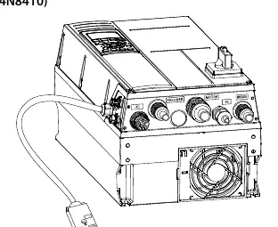
Cable Glands (134N8410)
The 134N8410 model includes specific cable glands:
- Encoder: EMC M20x1,5 (7.5–14.0 mm cable diameter).
- Motor: EMC M25x1,5 (10.0–18.0 mm cable diameter).
- Brake: EMC M20x1,5 (7.5–14.0 mm cable diameter).
- I/O: M25x1.5 (11–16 mm cable diameter).
Installation Notes
For complete installation details, refer to the VLT AutomationDrive FC 301/FC 302 Operating Instructions. For the 134N8410 model with MCO, also refer to the VLT Motion Control Option MCO 305 Operating Instructions.
Manufacturer information
Danfoss A/S
Practical help
Common problems
Capacitor discharge hazard
Wait at least 4 minutes after disconnecting power before servicing. Verify with a voltage meter.
UL Approval
Note that the FC 302 with connectors is not UL approved.
ETR Functionality
ETR functionality is not guaranteed in this configuration.
Before use
- Stop the motor.
- Disconnect AC mains and remote DC-link power supplies.
- Disconnect or lock the PM motor.
- Wait for capacitors to discharge (minimum 4 minutes).
- Verify zero voltage with a measuring device.
Specs in practice
- X1 Mains Connector
- 480V AC, max 15A (Pins 1-4); 30V DC, max 3A (Pins C-D).
- X2 Motor Connector
- 480V AC, max 15A (Pins 1-4); 30V DC, max 3A (Pins C-D).
- PROFIBUS Connector
- 30V DC, max 1A.
- Max Cable Length (Motor)
- 7.0 meters (23 ft).
Images and diagrams
- Illustrations 3.1 and 3.2 show the physical layout of 2 and 4 motor connectors respectively.
- Illustration 3.3 shows the mains connectors and cable glands for the 134N8410 model.
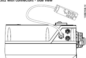
- Illustration 3.4 provides a side view of the connector placement.
Model compatibility
- Requires VLT AutomationDrive FC 301/FC 302 Operating Instructions for full installation.
- 134N8410 model requires VLT Motion Control Option MCO 305 Operating Instructions.

Manual page author
David Miller
Documentation analyst
Organizes user manual content into clear summaries, with attention to model details, product context, and everyday usability.