Industrial / Electrical
Installation Manual for Danfoss VLT® Midi Drive FC 280 Power Decoupling Plate
Quick installation guide for the Danfoss VLT® Midi Drive FC 280 power decoupling plate. Includes safety discharge times, required tools, and step-by-step mounting instructions for K1-K5 enclosure sizes.
Table of contents
Manual images
Click an image to enlargeQuick guide from the manual
This document provides instructions for installing the power decoupling plate on the Danfoss VLT® Midi Drive FC 280. Before starting, ensure you have the correct plate for your enclosure size (K1-K5). Important: The frequency converter contains DC-link capacitors that remain charged after power is removed. You must wait for the capacitors to discharge fully before performing any service. Refer to the discharge time table below.
Tools required
- Flat-edged screwdriver
- T20 screwdriver
Items supplied
The items included depend on the ordering number and enclosure size:
- 132B0373: I/O decoupling plate (K1), Power decoupling plate (K1), Screws (M4x12)
- 132B0374: Power decoupling plate (K2/K3), Screws (M4x12)
- 132B0375: Power decoupling plate (K4/K5), Screws (M4x12)
Installation for K1–K3 enclosure sizes
- Remove the earth screw (M6x12) from the frequency converter.
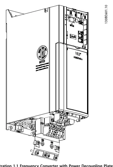
- Mount the power decoupling plate on the frequency converter and fasten it with the 2 supplied M4x12 screws. Tightening torque: 1.1–1.3 Nm.
- Remount the earth screw (M6x12). Tightening torque: 0.5–0.8 Nm.
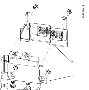
- For K1 enclosure size only: Mount the I/O decoupling plate onto the power decoupling plate using 2 M4x12 screws (tightening torque: 1.1–1.3 Nm) before mounting the assembly onto the frequency converter.
Installation for K4 and K5 enclosure sizes
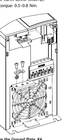
- Remove the earth plate from the frequency converter (K4 only).
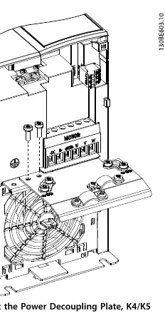
- Mount the power decoupling plate on the frequency converter and fasten it with the 2 supplied M4x12 screws. Tightening torque: 1.1–1.3 Nm.
- Remount the earth screw (M6x12). Tightening torque: 0.5–0.8 Nm.
Safety instructions
Before performing any service or repair work, stop the motor, disconnect AC mains and remote DC-link power supplies (including battery back-ups and UPS), and disconnect or lock the PM motor. Use an appropriate voltage measuring device to verify that capacitors are fully discharged.
Minimum waiting time for capacitor discharge
- 200–240 V (0.37–3.7 kW): 4 minutes
- 380–480 V (0.37–7.5 kW): 4 minutes
- 380–480 V (11–22 kW): 15 minutes
Manufacturer information
Danfoss A/S
Practical help
Common problems
Capacitor discharge risk
Wait 4 to 15 minutes (depending on voltage and power range) after disconnecting power before starting work.
Incorrect plate installation for K1
For K1 enclosures, the I/O decoupling plate must be mounted to the power decoupling plate before attaching the assembly to the converter.
Before use
- Verify enclosure size (K1, K2, K3, K4, or K5)
- Disconnect AC mains and remote DC-link power supplies
- Disconnect or lock PM motor
- Verify capacitor discharge with a voltage measuring device
- Ensure you have a flat-edged screwdriver and T20 screwdriver
Specs in practice
- Power decoupling plate torque
- 1.1–1.3 Nm
- Earth screw torque
- 0.5–0.8 Nm
Images and diagrams
- Illustration 1.1: Mounting the power decoupling plate on K2/K3 enclosures
- Illustration 1.2: Assembling the I/O decoupling plate to the power decoupling plate for K1
- Illustration 1.4: Removing the ground plate for K4 enclosures
- Illustration 1.5: Mounting the power decoupling plate for K4/K5 enclosures
Model compatibility
- K1 enclosure: Requires both I/O and Power decoupling plates.
- K4 enclosure: Requires removal of the existing earth plate before installation.

Manual page author
David Miller
Documentation analyst
Organizes user manual content into clear summaries, with attention to model details, product context, and everyday usability.