Industrial / Electrical
Installation Guide for Danfoss VLT® HVAC Drive FC 102 Remote Mounting Kit
Step-by-step installation guide for the Danfoss VLT® HVAC Drive FC 102 remote mounting kit. Includes mechanical installation, wiring, and safety procedures.
Table of contents
Manual images
Click an image to enlargeQuick Guide
This document provides instructions for the remote mounting of the Local Control Panel (LCP) for the Danfoss VLT® HVAC Drive FC 102. Before beginning, ensure the frequency converter was ordered with an LCP, as front covers ordered without LCPs do not have the necessary mounting holes.
Items Supplied
- LCP cables with 2 M12 connectors (3 m, 5 m, or 10 m lengths).
- Blind cover with M12 female connector.
- Base plate with D-sub connector and M12 male connector.
- Two gaskets and 1 nut for the D-sub connector.
- Intermediate cover with the front cover.
- Disassembly tool.
Additional items required: Local control panel (LCP) and four M4 self-tapping screws.
Mechanical Installation
Installing the Blind Cover
- Remove the front cover from the frequency converter.
- Remove the LCP from the front cover.
- Install the blind cover with the gasket and the M12 connector.
- Reinstall the front cover on the frequency converter.
Mounting the Remote LCP
- Drill a 24 mm (±1 mm) hole in the wall. Ensure the hole is perpendicular to the wall (±1°). The kit is suitable for insulated walls 30–90 mm thick and solid walls 1–20 mm thick.
- Install the base plate with the D-sub connector using the gasket and 4 self-tapping screws.
- Secure the nut on the D-sub connector with a torque of 1.5 Nm (13 in-lb). Ensure the base plate and nut are tight on both sides of the wall.
- Mount the LCP with the gasket on the base plate. Insert the rubber flap into the opening at the top of the cradle.
- Mount the intermediate cover and lid on the base plate. Connect the top of the lid to the cradle and push until it clicks. The unit with this cover has an IP54 rating.
Electrical Installation
Connect the M12 connectors on the blind cover and the LCP using the supplied cable.
Using the Remote LCP
- The On, Warn., and Alarm indicator lights are visible with the closed front cover at an angle up to 45°.
- Lock the front cover using the rings at the bottom of the cover.
- Open the front cover using the groove at the side of the cover.
- The cover includes a designated place for a label.
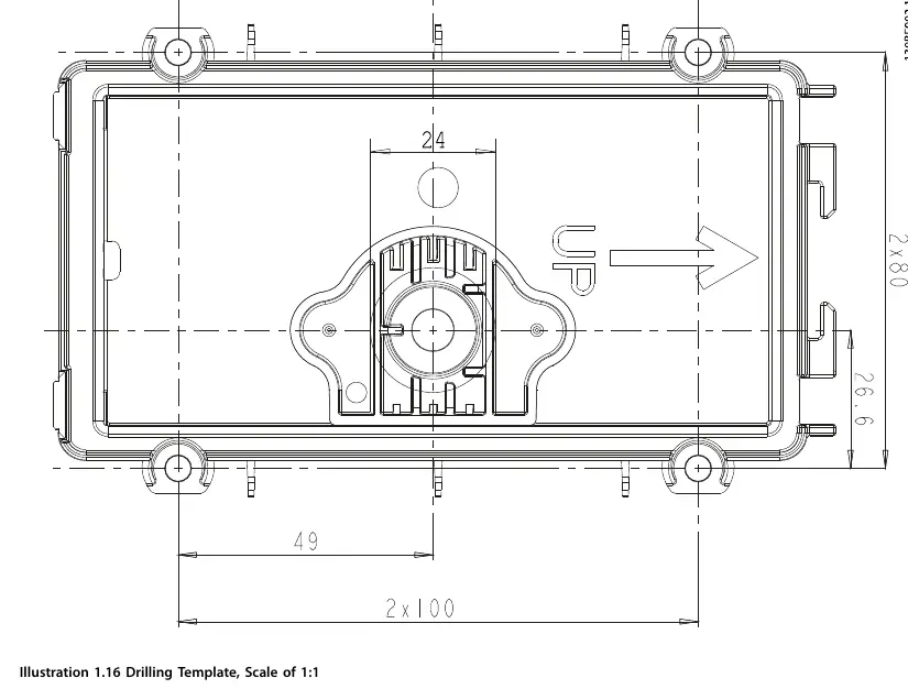
Drilling Template
Use the provided drilling template (scale 1:1) to mark the hole locations on the wall before drilling.
Manufacturer information
Danfoss A/S
Practical help
Common problems
LCP cannot be mounted to the frequency converter front cover.
Verify that the frequency converter was ordered with an LCP. Front covers ordered without LCPs do not have the required mounting holes.
Wall thickness compatibility.
The kit is designed for insulated walls 30–90 mm thick or solid walls 1–20 mm thick.
High voltage hazard during service.
Always wait for the DC-link capacitors to discharge fully before performing service. Refer to the discharge time table in the manual based on your specific voltage and power rating.
Before use
- Stop the motor.
- Disconnect AC mains and remote DC-link power supplies (including battery back-ups and UPS).
- Disconnect or lock the PM motor.
- Wait for the capacitors to discharge fully (refer to Table 1.2).
- Use a voltage measuring device to confirm capacitors are fully discharged.
- Ensure you have the correct cable length (3m, 5m, or 10m).
Specs in practice
- Hole diameter
- 24 mm ±1 mm (1 in ±0.04 in).
Images and diagrams
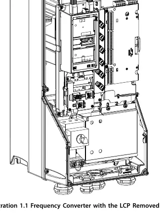
- Illustration 1.1: Shows the frequency converter with the LCP removed.
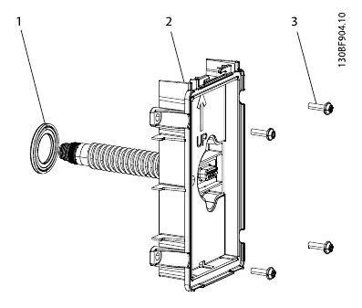
- Illustration 1.3: Exploded view of the base plate assembly with the D-sub connector.
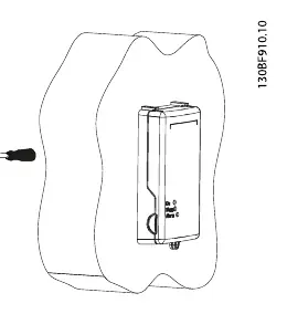
- Illustration 1.11: Wiring diagram showing the connection between the blind cover on the drive and the remote LCP.
- Illustration 1.16: Drilling template for wall mounting.
Model compatibility
- Valid for frequency converters ordered with LCP.
- Not compatible with front covers ordered without LCPs.

Manual page author
Emily Carter
User documentation editor
Prepares concise manual descriptions and highlights the most useful setup, operation, and maintenance information for readers.