Industrial / Electrical
Bus Decoupling Kit for Danfoss VLT Midi Drive FC 280
Installation guide for the Danfoss Bus Decoupling Kit (132B0369) for VLT Midi Drive FC 280. Includes mounting instructions for horizontal and vertical plates, cable fixation steps, and critical safety discharge warnings.
Table of contents
Manual images
Click an image to enlargeQuick guide from the manual
This document provides installation instructions for the Bus Decoupling Kit (132B0369) designed for the Danfoss VLT Midi Drive FC 280. The kit ensures mechanical fixation and electrical screening of cables for control cassettes (PROFIBUS, PROFINET, CANopen, and Ethernet). Important: Always observe the discharge time for DC-link capacitors before performing any service or repair work.
Items Supplied
- 1 Horizontal decoupling plate
- 1 Vertical decoupling plate
- 4 M3x6 screws
Safety Instructions
The frequency converter contains DC-link capacitors that remain charged even when the power is off. Before performing any work:
- Stop the motor.
- Disconnect AC mains and remote DC-link power supplies (including battery back-ups, UPS, and other frequency converters).
- Disconnect or lock the PM motor.
- Wait for the capacitors to discharge fully. The minimum waiting time is 4 minutes for power ranges up to 7.5 kW (380-480V) or 200-240V, and 15 minutes for 11-22 kW (380-480V).
- Use a voltage measuring device to verify that capacitors are fully discharged.
Mounting Instructions
Follow these steps to install the kit:
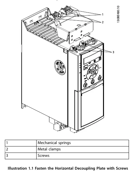
- Horizontal Plate: Place the horizontal decoupling plate on the control cassette mounted on the frequency converter. Fasten it using 2 screws. Tightening torque: 0.7–1.0 Nm.
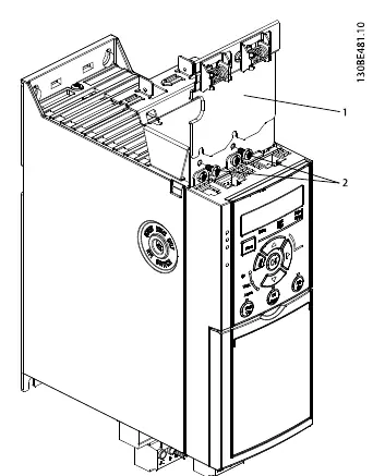
- Vertical Plate (Optional): If required, remove the 2 mechanical springs and 2 metal clamps from the horizontal plate. Mount these components onto the vertical plate. Fasten the vertical plate with 2 screws. Tightening torque: 0.7–1.0 Nm.
Notice: Do not mount the vertical decoupling plate if the IP21 top cover is used, as it will interfere with the cover installation.
Cable Connection
- Push the cable connectors (PROFIBUS/PROFINET/CANopen/Ethernet) into the sockets in the control cassette.
- Fixation: Place the cables between the spring-loaded metal clamps to establish mechanical fixation and electrical contact between the screened sections of the cables and the clamps.
Manufacturer information
Danfoss A/S
Practical help
Common problems
Vertical plate does not fit or interferes with the top cover.
Do not mount the vertical decoupling plate if the IP21 top cover is used.
Unsure about cable fixation.
Ensure cables are placed between the spring-loaded metal clamps to establish mechanical fixation and electrical contact.
Before use
- Verify the control cassette type (PROFIBUS, PROFINET, CANopen, or Ethernet).
- Ensure the frequency converter is powered off.
- Wait for the DC-link capacitors to discharge (4-15 minutes depending on power range).
- Check if the IP21 top cover is installed.
- Have a torque screwdriver ready (0.7–1.0 Nm).
Specs in practice
- Tightening torque
- 0.7–1.0 Nm for mounting screws.
- Discharge time (200–240V)
- 4 minutes.
- Discharge time (380–480V, 0.37–7.5 kW)
- 4 minutes.
- Discharge time (380–480V, 11–22 kW)
- 15 minutes.
Images and diagrams
- Illustration 1.1 shows the installation of the horizontal decoupling plate.
- Illustration 1.2 shows the installation of the vertical decoupling plate.
Model compatibility
- Compatible with VLT Midi Drive FC 280 control cassettes: PROFIBUS, PROFINET, CANopen, and Ethernet.
- Vertical decoupling plate is incompatible with the IP21 top cover.

Manual page author
Michael Turner
Technical manual editor
Reviews PDF manuals for structure, safety notes, and practical product details so readers can find the right information quickly.