HVAC / Thermostats & Controls
Operating Instructions for Danfoss BD Controller 101N07xx Series
Quick guide for the Danfoss BD Controller 101N07xx Series. Learn about installation, wiring, software configuration, parameter settings, and troubleshooting for 48V DC compressor systems.
Table of contents
Manual images
Click an image to enlargeQuick guide from the manual
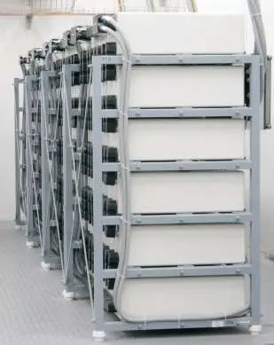
The Danfoss BD Controller 101N07xx Series is designed for 48V DC compressor systems, primarily used in shelter cooling, battery cooling for radio stations, and secondary applications like mobile cooling. This manual covers the installation, software configuration, and parameter settings required to operate the controller effectively.
Installation and Wiring
Installation involves preparing the necessary components, connecting cables, and configuring the software. Ensure you have the following items before starting:
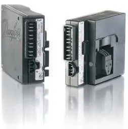
- BD electronic controller (101N0720 or 101N0730)
- Tool4Cool LabEdition software installation CD
- NTC temperature sensor or mechanical thermostat
- DC line cords
- Danfoss One Wire/LIN gateway (if using PC interface)
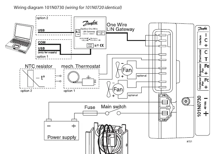
Wiring Connections:
- I, C, +: Modbus data communication.
- C, T: Thermostat connection (NTC sensor or mechanical ON/OFF thermostat).
- Fe, +: Evaporator fan (Optional, 48V DC, max 60W).
- Fc, +: Condenser fan (Optional, 48V DC, max 60W).
- -, +: Main supply voltage (Nominal 48V DC, range 32-60V DC).
Refer to the wiring diagram in the manual for specific terminal layouts and gateway connections.
Software Configuration
The controller can be programmed and optimized using the Danfoss Tool4Cool LabEdition software. This software allows users to:
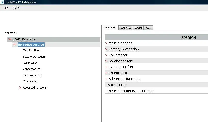
- Observe and document compressor operation via data logs and plots.
- Change controller parameters.
- Copy settings from one controller to another.
- Perform optimization of specific parameters before mass production.
For brief installation instructions, refer to the BD Controller 101N07xx Series 48 V DC with Tool4Cool LabEdition Software - Quick Start Guide.
Operation and Parameters
The controller manages various functions to ensure efficient operation and protection of the system:
- Main Functions: Includes Main Switch (ON/OFF) and monitoring of battery, NTC sensor, and PCB temperature.
- Battery Protection: Prevents permanent battery damage by cutting out if voltage drops below the set level (32-60V range).
- Compressor Control: Speed is set via the Requested speed parameter. The system includes protection against operation below minimum speed (1850 rpm) and above maximum speed (4700 rpm for BD250GH, 4300 rpm for BD350GH).
- Fan Control: Condenser and evaporator fans can be synchronized with compressor operation or forced ON.
- Thermostat: Supports both electronic (NTC) and mechanical thermostats.
- ECO Function: Optimizes compressor speed based on temperature to reduce energy consumption and noise.
Troubleshooting and Safety
The controller includes an alarm function to notify users of system errors. The Actual error parameter displays the following codes:
- 1: Voltage failure
- 2: Fan failure
- 3: Motor failure
- 4: Min. speed failure
- 5: Max. speed failure
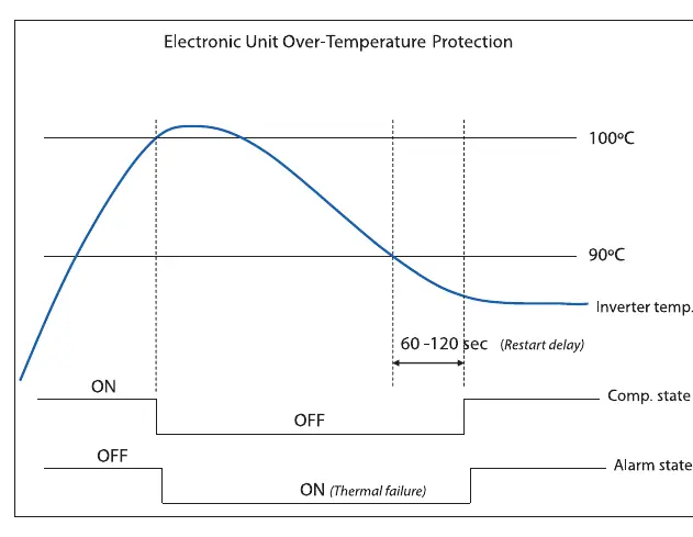
- 6: Thermal failure (Inverter temperature > 100°C)
- 7: NTC Sensor Failure
The system includes automatic restart delays (default 60 seconds) after failures to prevent short cycling.
Manufacturer information
Danfoss A/S
Practical help
Common problems
Compressor stops unexpectedly
Check for battery voltage failure, motor/fan failure, or thermal failure (inverter temperature > 100°C). Check the 'Actual error' parameter.
Communication lost with master controller
Verify Modbus connection and check 'Communication timeout' settings. The controller may stop the compressor if communication is lost.
NTC sensor error
Ensure the sensor is connected correctly. An error is sent if temperature is > +100°C or < -60°C.
Before use
- Verify 48V DC power supply (32-60V range).
- Ensure cable cross-section matches the length requirements.
- Install Tool4Cool LabEdition software on a PC.
- Connect NTC sensor or mechanical thermostat to terminals C & T.
- Check for required accessories (Gateway, cables) if using PC interface.
Specs in practice
- Requested speed
- Defines compressor speed and capacity; adjustable via software.
- Battery cutout level
- Voltage threshold to prevent battery damage; adjustable from 32V to 60V.
Images and diagrams
- Wiring diagram: Shows connections for power, thermostat, fans, and communication gateway.
- Battery protection graph: Illustrates cut-in/cut-out voltage levels and restart delays.
- Compressor speed protection: Shows min/max speed limits and restart delays.
- Inverter temperature protection: Shows shutdown at 100°C and restart after cooling below 90°C.
Model compatibility
- Compatible with BD250GH and BD350GH compressors.
- Requires Tool4Cool LabEdition software for advanced configuration.
- Supports NTC temperature sensors or mechanical ON/OFF thermostats.

Manual page author
Michael Turner
Technical manual editor
Reviews PDF manuals for structure, safety notes, and practical product details so readers can find the right information quickly.