HVAC / Thermostats & Controls
User Manual for Danfoss 102E5 Electro Mechanical Mini Programmer
Quick guide for the Danfoss 102E5 electro-mechanical mini programmer. Learn how to install, wire, set the time, program heating schedules, and use manual overrides.
Table of contents
Manual images
Click an image to enlargeQuick guide from the manual
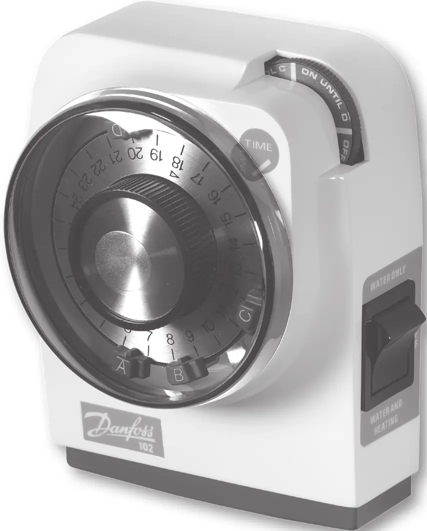
The Danfoss 102E5 is an electro-mechanical mini programmer designed to control hot water and heating systems. It features a 24-hour clock dial with adjustable tappets for setting ON/OFF periods and a rocker switch for selecting operating modes. Important: This device must be installed by a qualified electrician or heating installer in accordance with IEEE wiring regulations. Always ensure the protective tape is removed from the pre-selector wheel before putting the unit into service.
Product Overview
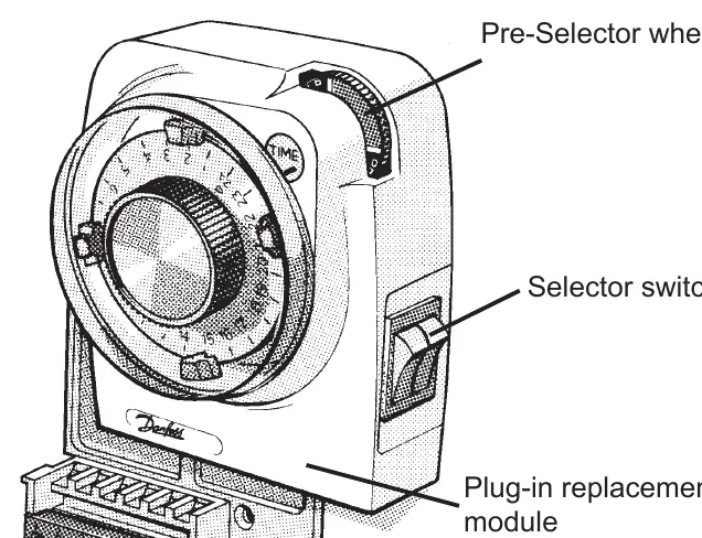
The unit consists of a plug-in module and a wallplate/terminal block. Key controls include:
- Pre-Selector Wheel: Used for temporary overrides and manual control.
- Selector Switch (Rocker): Selects between Hot Water only, Hot Water & Heating together, or System OFF.
- Clock Dial: Displays the time and holds the tappets for programming.
- Tappets: Red tappets set the ON times, and Blue tappets set the OFF times.
Installation and Wiring
Installation should only be performed by a professional. Follow these steps:
- Loosen the fixing screw in the base to release the wiring cover.
- Fix the wallplate/terminal block to the wall using appropriate screws or a standard steel box.
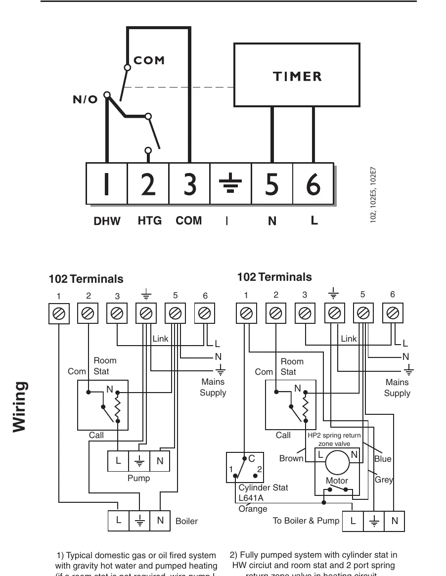
- Connect the unit according to the wiring diagrams. Ensure terminals 3 and 6 are linked for mains voltage applications using insulated cable.
- Plug the module firmly into the wallplate until it clicks into place.
- Replace the wiring cover and tighten the fixing screw.
- Switch on the mains and test the operation by rotating the clock dial two full revolutions.
Setting the Time
The unit uses a 24-hour clock. To set the time:
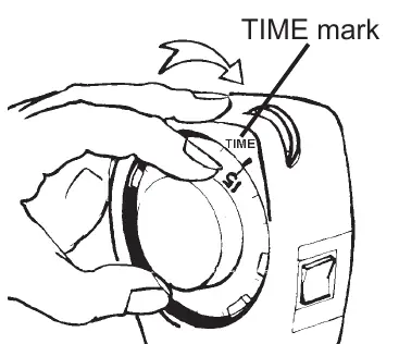
- Remove the dial cover by turning it slightly to the left and pulling it off.
- Turn the dial clockwise only until the correct time aligns with the TIME mark.
- Replace the dial cover.
Note: You must reset the time after a power cut or when clocks change in Spring and Autumn.
Setting the Program
You can set up to 2 ON and 2 OFF periods per day:
- Remove the dial cover.
- Grip the dial knob and slide the RED tappets to the desired ON times.
- Slide the BLUE tappets to the desired OFF times.
- Tappets may be stiff; they can be moved clockwise or anti-clockwise.
- Rotate the dial clockwise at least twice to clear the mechanism.
Operating Modes
Use the rocker switch on the side of the unit to select the desired mode:
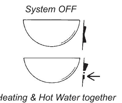
- Hot Water Only: Selects hot water control.
- Hot Water & Heating Together: Selects both systems.
- System OFF: Turns both systems off.
The current status is displayed on the wheel at the top right corner of the unit.
Temporary Overrides
The pre-selector wheel allows you to override the current program without changing the settings:
- Turn the wheel anti-clockwise to switch the unit ON when it is OFF, or OFF when it is ON.
- The system will revert to the programmed schedule at the next operation.
- Useful settings: Turn to "ON UNTIL D" for All Day ON, or "OFF UNTIL A" for All Day OFF.
Technical Specifications
- Power supply: 230Vac ± 15%, 50 Hz
- Switching action: 1 x SPST, Type 1B
- Max. Switch rating: 264Vac, 50/60Hz, 6(2)A
- Timing Accuracy: ±1 min./month
- Enclosure Rating: IP20
- Max. Ambient Temperature: 55°C
- Dimensions: 112 x 135 x 69 mm
Manufacturer information
Danfoss A/S
Practical help
Common problems
Time is incorrect
Reset the time after a power cut or when clocks change in Spring/Autumn.
Tappets are difficult to move
Tappets may be stiff; they can be moved in either a clockwise or anti-clockwise direction.
System not operating as expected
Ensure terminals 3 and 6 are linked for mains voltage applications and that the protective tape has been removed.
Before use
- Ensure the installer has removed the protective tape covering the pre-selector wheel.
- Rotate the clock dial two complete revolutions clockwise to clear the mechanism.
- Check that all positions of the Selector Switch operate correctly.
- Verify that the wiring matches the specific system type (e.g., gravity hot water vs. fully pumped).
Images and diagrams
- Wiring diagrams are provided for typical domestic gas/oil systems and fully pumped systems with cylinder stats.
- Terminals 3 and 6 must be linked for mains voltage applications.
Model compatibility
- Designed for controlling hot water and heating systems.
- Must be installed by a qualified electrician or competent heating installer.

Manual page author
David Miller
Documentation analyst
Organizes user manual content into clear summaries, with attention to model details, product context, and everyday usability.