HVAC / Thermostats & Controls
Braeburn 1025NC Non-Programmable Thermostat
Quick guide for the Braeburn 1025NC non-programmable thermostat. Includes installation steps, wiring diagrams, system testing, and maintenance instructions.
Table of contents
Manual images
Click an image to enlargeQuick Guide
The Braeburn 1025NC is a non-programmable thermostat designed for single-stage heat-only systems. It requires 24 Volt AC power or two AA alkaline batteries for operation. If using 24V AC power, batteries can serve as a backup. Always turn off power to the heating equipment before beginning installation.
Product Overview
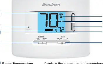
The thermostat features a digital display showing room temperature, set temperature, and system status. Controls include a System switch (OFF/HEAT) and a Fan switch (AUTO/ON). A reset button is located on the front for restoring factory defaults.
Installation
Follow these 5 basic steps to install your thermostat:
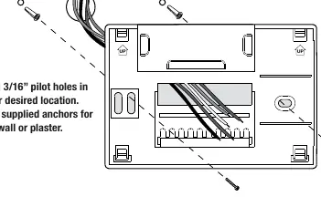
- Install the Sub-Base: Remove the sub-base from the thermostat body. Drill 3/16 inch pilot holes and mount the base using supplied anchors.
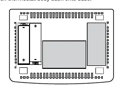
- Provide Power: Connect the common side of the transformer to the C terminal for 24V AC power. Alternatively, insert two AA alkaline batteries in the rear housing.
- Connect Your Wires: Connect wires according to the terminal functions (R, G, W1, V3, C).
- Set Installer Switches: Configure the F/C and HE/HG switches based on your system requirements.
- Attach Thermostat: Line up the body with the sub-base and push until it snaps into place.
Wiring Connections
The terminal functions are as follows:
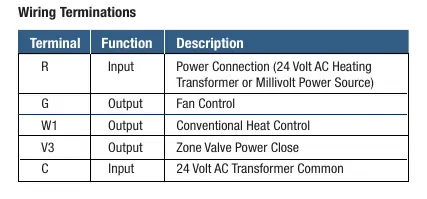
- R: Power Connection (24V AC or Millivolt)
- G: Fan Control
- W1: Conventional Heat Control
- V3: Zone Valve Power Close
- C: 24 Volt AC Transformer Common
Installer Switches
Adjust these switches before attaching the thermostat to the sub-base:
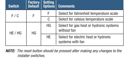
- F/C: Select F for Fahrenheit or C for Celsius.
- HE/HG: Select HG for gas heat or hydronic systems without a fan; select HE for electric heat or hydronic systems with a fan.
Note: Press the reset button after changing installer switches.
Operation
Use the switches on the front of the unit to control your system:
- System Switch: Set to HEAT to operate the heating system or OFF to turn it off.
- Fan Switch: Set to AUTO for the fan to run only when required by the system, or ON for continuous fan operation.
- Temperature Adjustment: Use the arrow buttons to adjust the set point temperature.
Maintenance
If batteries are installed, a low battery indicator will appear on the display when they need replacement. Replace batteries annually or if the thermostat will be unattended for an extended period. To clean, use a soft damp cloth; never spray liquid directly on the thermostat or use abrasive cleansers.
System Testing
Do not short across terminals to test the system. To test: move the System switch to HEAT, raise the set temperature 3 degrees above room temperature, and verify the system starts. Move the Fan switch to ON to verify the fan starts, then back to AUTO to stop it.
Manufacturer information
Braeburn Systems LLC
Practical help
Common problems
System does not start
Ensure the System switch is in HEAT mode and the set temperature is at least 3 degrees above room temperature. Check wiring connections.
Low battery indicator on display
Replace the two AA alkaline batteries immediately.
Incorrect temperature scale (F/C)
Adjust the F/C installer switch and press the reset button.
Before use
- Turn off power to the heating equipment.
- Verify system compatibility (Single stage heat only, 24V AC, or 250-750mV).
- Ensure you have a 3/16 inch drill bit for mounting.
- Check wiring configuration against the manual's terminal table.
- Install two AA alkaline batteries if not using 24V AC power.
Specs in practice
- Electrical Rating
- 24 Volt AC (1 amp maximum load per terminal).
- Control Range
- 45° – 90° F (7° – 32° C).
- Temperature Accuracy
- +/- 1° F (+/- .5° C).
Images and diagrams
- Wiring Terminations: Defines the function of terminals R, G, W1, V3, and C.
- Sub-base mounting: Illustrates drilling pilot holes and securing the base to the wall.
Model compatibility
- Compatible with single stage heat only systems.
- Compatible with 250 – 750 millivolt heat only systems.
- Compatible with 2 or 3 wire hydronic zone systems.

Manual page author
David Miller
Documentation analyst
Organizes user manual content into clear summaries, with attention to model details, product context, and everyday usability.