HVAC / Thermostats & Controls
Danfoss 102E5 Electronic Mini Programmer User Guide
Quick guide for the Danfoss 102E5 electronic mini-programmer. Includes installation, wiring diagrams, programming instructions for 24-hour or 5/2 day modes, and troubleshooting.
Table of contents
Manual images
Click an image to enlargeQuick guide from the manual
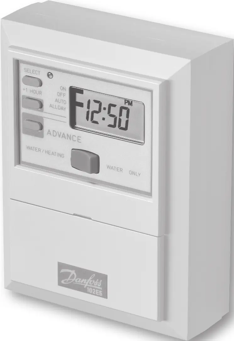
The Danfoss 102E5 is an electronic mini-programmer designed to control hot water and heating systems. It supports both 24-hour and 5/2 day programming modes. Important: This product must be installed by a qualified electrician or competent heating installer in accordance with IEEE wiring regulations. The unit features a battery backup that retains settings for up to 15 days during power cuts.
Installation and Wiring
The unit consists of a wallplate and a module. To install:
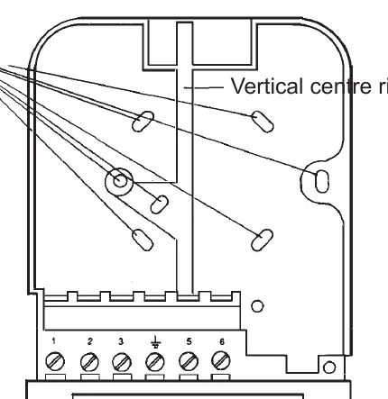
- Loosen the fixing screw in the base to release the wiring cover.
- Separate the wallplate from the module.
- Fix the wallplate to the wall or plaster box, ensuring screw heads do not protrude beyond the vertical centre rib.
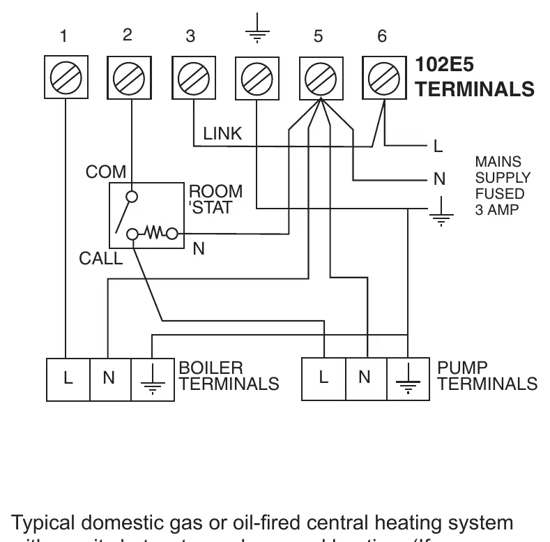
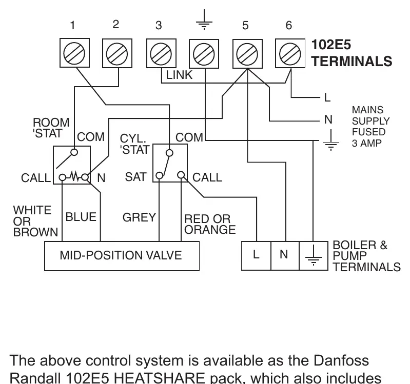
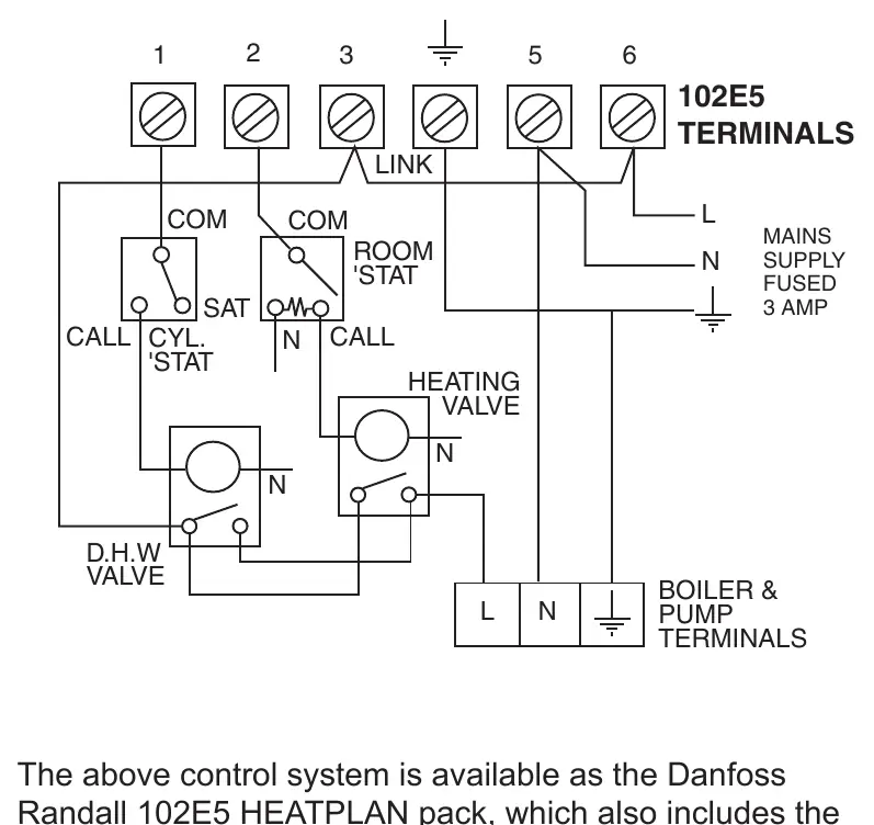
- Connect the wiring according to the specific system requirements (Gravity DHW, 3-port mid-position valve, or 2-port zone valves).
- Plug the module into the wallplate, ensuring the hook at the top engages.
If the system is 230Vac, terminals 3 and L must be linked with insulated cable. For FRU (Factory Replacement Units), follow the specific replacement instructions provided in the manual.
Setting the Clock and Programme
Before initial use, reset the unit by pressing the SELECT, ADVANCE, +, and - buttons simultaneously. This sets the time to 12:00pm on Monday and reinstates factory presets.
Setting the Clock
- Press PROGRAMME once.
- Use + and - buttons to set the correct time.
- Press PROGRAMME again to confirm.
Programming Modes
The unit offers 24-hour control (same programme daily) or 5/2 day control (weekdays/weekends). To convert to 5/2 day mode, remove the small two-way connector from the pins on the rear of the module and reset the unit.
Operation and Overrides
Use the rocker switch under the LCD to select WATER/HEATING or WATER ONLY. Press the SELECT button to cycle through modes:
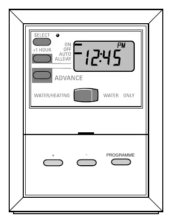
- ON: Heating/hot water remains on constantly.
- OFF: Heating/hot water will not come on.
- AUTO: Follows programmed times.
- ALLDAY: Comes on at the first programmed ON and stays on until the last programmed OFF.
Temporary Overrides:
- +1 HOUR: Adds an extra hour of operation. Press again to cancel.
- ADVANCE: Advances to the next programmed event. Press again to cancel.
Technical Specifications
- Power supply: 230V ± 15%, 50Hz
- Switching action: 1 x SPST, Type 1B
- Enclosure Rating: IP30
- Power Reserve: Minimum 14 days
- Max. Ambient Temperature: 45°C
Manufacturer information
Danfoss A/S
Practical help
Common problems
Unit not operating as expected
Check the rocker switch position (WATER/HEATING vs WATER ONLY) and ensure the SELECT mode is set to AUTO.
System not responding to programme
Ensure the unit is in AUTO mode. If in OFF or ON, the programme will not be followed.
Power cut occurred
The unit retains settings for 15 days. When power is restored, press the PROGRAMME button to reactivate; you may need to reset the time and day.
Before use
- Ensure installation is performed by a qualified electrician.
- Verify wiring connections against the specific system diagram (Gravity, 3-port, or 2-port).
- Reset the unit by pressing SELECT, ADVANCE, +, and - simultaneously.
- Set the current time and day.
- Choose between 24-hour or 5/2 day programming mode.
Specs in practice
- Power supply
- 230V ± 15%, 50Hz
- Switching action
- 1 x SPST, Type 1B
- Enclosure Rating
- IP30 (Protected against solid objects over 2.5mm)
- Power Reserve
- Minimum 14 days of memory retention without mains power
Images and diagrams
- Wiring diagrams are provided for Gravity DHW with Pumped Heating, 3-port mid-position valve systems, and 2-port zone valve systems.
- The wallplate terminal identification is clearly marked for connections 1, 2, 3, 5, and 6.
Model compatibility
- Compatible with various heating systems; refer to the replacement table in the manual for specific wiring compatibility with older models like Randall 102, 3020P, and Horstmann Diamond series.

Manual page author
Michael Turner
Technical manual editor
Reviews PDF manuals for structure, safety notes, and practical product details so readers can find the right information quickly.