HVAC / Thermostats & Controls
Operating Instructions for Danfoss 101N08xx Series Controller
Quick guide for the Danfoss 101N08xx Series 12-24V DC controller. Includes installation steps, wiring diagrams, parameter settings, and software configuration for Tool4Cool.
Table of contents
Manual images
Click an image to enlargeQuick Guide
The Danfoss 101N08xx Series is a 12-24V DC controller designed for BD compressors. It is used in mobile refrigeration, air cargo cooling, and various cooling applications. The system supports single or twin compressor configurations and can be programmed via the Tool4Cool LabEdition software.
Installation and Wiring
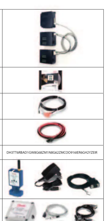
Before installation, ensure you have the necessary components: the controller module, appropriate cables, an NTC temperature sensor or mechanical thermostat, and a compatible gateway (Bluetooth or One Wire/LIN) if remote configuration is required.
Cable Connection
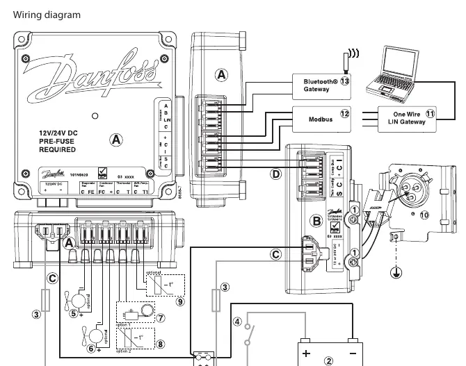
- Single Compressor: Connect the 12V or 24V DC line cord, communication cable, and display cable as shown in the wiring diagram.
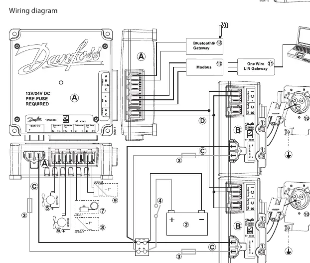
- Twin Compressor: Connect both compressor modules to the application module using the twin compressor communication cable assembly.
Always ensure the correct voltage (12V or 24V) is used for the specific compressor module.
Software Interface
The controller is programmed and optimized using the Tool4Cool LabEdition software on a PC. This interface allows users to:
- Observe real-time measurements (power consumption, speed, temperature).
- Change controller parameters.
- Access error and event logs.
- Copy settings between controllers.
Parameter Configuration
The controller features various parameter groups that can be adjusted:
- Main Functions: Includes the main switch and power consumption monitoring.
- Battery Protection: Sets voltage cut-out and cut-in levels to prevent battery damage.
- Compressor Settings: Controls requested speed, start delay, and start speed.
- Fan Control: Synchronizes condenser and evaporator fan speeds with compressor operation.
- Thermostat: Supports NTC sensors or mechanical thermostats with adjustable cut-out temperatures and differentials.
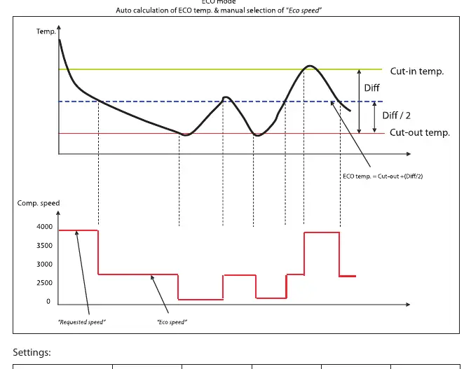
- ECO Function: Optimizes compressor speed based on temperature to reduce energy consumption.
- Communication: Configures Modbus address and communication speed.
Safety and Protection
The controller includes built-in safety features:
- Short Cycling Prevention: A minimum restart delay (default 60 seconds) is enforced.
- Overheating Protection: If the PCB temperature reaches 100°C, the system shuts down and triggers a thermal failure alarm. It restarts automatically once the temperature drops below 90°C.
- Under-temperature Protection: Protects compressor magnets from damage due to extremely low temperatures.
- Error Logs: Detailed logs are available to assist in service situations, recording the sequence and nature of failures.
Manufacturer information
Danfoss A/S
Practical help
Common problems
Communication lost
The system will stop. Check the connection to the MMI or gateway. The system will restart automatically once a valid frame is detected on the bus.
Compressor failure
Check the error log for specific codes: 1 (Battery protection), 2 (Fan failure), 3 (Motor failure), 4 (Min. speed failure), 5 (Thermal failure), 6 (NTC failure), 7 (Communication error).
Short cycling
The controller has a built-in restart delay (default 60 seconds) to prevent damage. Wait for the delay to expire.
System overheating
If the PCB reaches 100°C, the system shuts down. Ensure proper ventilation and wait for the temperature to drop below 90°C for an automatic restart.
Before use
- Verify the power supply is 12V or 24V DC.
- Confirm if the setup is a single or twin compressor configuration.
- Ensure an NTC temperature sensor or mechanical thermostat is connected.
- Install the Tool4Cool LabEdition software on your PC.
- Check that the correct gateway (Bluetooth or One Wire/LIN) is available if needed.
Specs in practice
- Battery cutout level
- The voltage threshold at which the controller stops the compressor to prevent permanent battery damage.
- Requested speed
- Sets the compressor RPM, directly impacting cooling capacity.
- Restart delay
- The mandatory wait time before the compressor can restart, preventing short cycling.
Images and diagrams
- Wiring diagrams illustrate the connection points for power, communication, and sensors for both single and twin compressor setups.
Model compatibility
- Compatible with R134a and R404A/R507 compressors.
- Requires matching voltage (12V or 24V) for the specific compressor module.

Manual page author
Emily Carter
User documentation editor
Prepares concise manual descriptions and highlights the most useful setup, operation, and maintenance information for readers.