Home / Security
Installation Guide for Danfoss Gas Sensor Type DGS
A comprehensive installation and configuration guide for the Danfoss DGS gas sensor. Includes detailed wiring diagrams, sensor replacement procedures, troubleshooting steps, and technical specifications for various gas types.
Table of contents
Manual images
Jump to the sectionQuick Guide
The Danfoss DGS is a digital gas sensor designed for safety applications. It must be installed by a qualified technician in accordance with local industry standards. The device is a safety component that provides alarm functions but does not address the root cause of gas leaks.
Key Installation Requirements:
- ESD Protection: Ensure your body is at ground potential during installation to avoid damage.
- Location: For gases heavier than air (HFC, CO2, Propane), mount the sensor head approximately 30 cm (12 inches) above the floor, preferably in the airflow.
- Orientation: The sensor head must always be mounted pointing downwards.
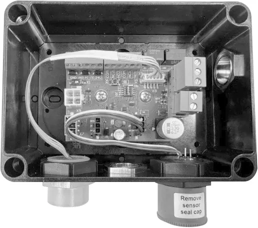
- Protection: Remove the sensor protection cap only after all silicones are dry and before energizing the device.
Installation and Wiring
To wall mount the DGS, unscrew the lid by releasing the four plastic screws in the corners. Mount the base to the wall using the screw holes. Re-apply the lid after wiring.
Cable Gland Opening: The enclosure is pre-drilled. If additional holes are needed, use a sharp screwdriver and small hammer to punch holes, ensuring no damage to internal components. Remove burrs and install cable glands according to the enclosed guide.
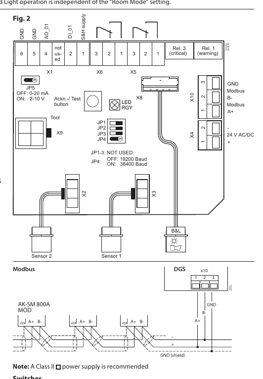
Wiring: Refer to the connection diagram (Fig. 2) for terminal positions. Ensure technical requirements for electrical security are met. The device supports 24V DC or 24V AC power. If using the analog output (AO_01), ensure the connected device shares the same ground potential.
Configuration
The DGS is pre-configured with factory defaults. Use the internal switches to adjust settings:
- JP4: Adjusts MODBUS baud rate (OFF: 19200, ON: 38400). Power cycle the device after changing this setting.
- JP5: Adjusts analog output type (OFF: 0-20 mA, ON: 0-10 V).
To integrate with a Danfoss system manager or BMS, set the MODBUS address using the DGS Service Tool (password: 1234).
Sensor Replacement
The sensor is connected via a plug, allowing for simple exchange without on-site calibration. The internal routine automatically recognizes the new sensor and restarts measurement. If the sensor type or range does not match the configuration, the status LED will indicate an error.
Testing and Maintenance
Regular testing is required to maintain performance:
- Functional Test: Press the test button for more than 8 seconds to simulate alarms and verify output functions.
- Bump Test/Calibration: Recommended annually for DGS-SC and DGS-PE. DGS-IR requires calibration every 60 months, with an annual bump test recommended.
- Warning: Do not spray or pour pure refrigerant or liquids onto the sensor head for testing, as this may destroy it.
Troubleshooting
The DGS features self-monitoring with LED status indicators:
- LED Off: Check power supply and wiring.
- Green Flashing: Calibration interval exceeded or sensor end-of-life.
- Yellow: Sensor disconnected, wrong type, or supply voltage out of range.
- Yellow Flashing: Device is in service mode (via Service Tool).
- Alarms in absence of leak: Try setting an alarm delay or perform a bump test.
Technical Specifications
The DGS supports various sensor types with specific ranges:
- DGS-IR (CO2): 0-20000 ppm, 60-month calibration interval.
- DGS-SC (HFC): 0-2000 ppm, 12-month calibration interval.
- DGS-PE (Propane): 0-5000 ppm, 12-month calibration interval.
- Power Supply: 24V DC ± 20% or 24V AC -10%/+15%.
- Enclosure: IP65.
Manufacturer information
Danfoss A/S
Practical help
Common problems
LED is off
Check power supply and wiring. Verify if the unit was damaged in transit.
Green LED is flashing
Calibration interval has been exceeded or sensor has reached end of life. Perform calibration or replace the sensor.
Yellow LED is on
Check if the sensor is properly connected, matches the specification, or if supply voltage is out of range.
Yellow LED is flashing
The device is in service mode. Change the setting or wait for the 15-minute time-out.
Alarms trigger without a leak
Set an alarm delay or perform a bump test to ensure proper operation.
Before use
- Ensure body is at ground potential to avoid ESD damage.
- Remove the sensor protection cap before operation.
- Mount the sensor head pointing downwards.
- Verify the cable type and mounting height.
- Check MODBUS address and baud rate settings.
- Ensure the sensor type matches the DGS specification.
Images and diagrams
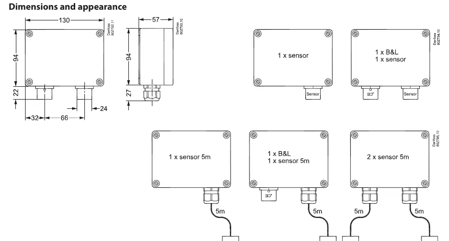
- Fig 1: Dimensions and appearance showing mounting orientation.
- Fig 2: Wiring diagram for sensors, relays, MODBUS, and power supply.
Model compatibility
- Compatible with Danfoss system manager or general BMS.
- Requires 24V DC or 24V AC power supply.
- Supports MODBUS communication.

Manual page author
Emily Carter
User documentation editor
Prepares concise manual descriptions and highlights the most useful setup, operation, and maintenance information for readers.