Home / Security
Installation Guide for Danfoss Gas Sensor Strobe and Horn
Quick installation and configuration guide for the Danfoss Gas Sensor Strobe and Horn (080Z2822). Includes wiring diagrams, sound settings, and technical specifications.
Table of contents
Manual images
Jump to the sectionQuick guide from the manual
The Danfoss Gas Sensor Strobe and Horn (Code no. 080Z2822) is a signaling device designed for 12–24 V DC operation. This guide covers the installation, wiring, and sound configuration. Installation must be performed by qualified personnel. Ensure the power supply is disconnected before servicing.
Technical specifications
- Operating voltage: 12 – 24 V DC
- IP rating: IP 65
- Operating temperature: -40 to +55 °C
- Sound output: Intermittent 1000 Hz, max 94 dB(A)
- Tones: 32 user-selectable tones
- Lens colour: Red
- Material: PC
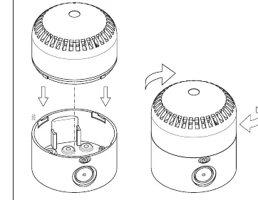
Installation and assembly
The device features a twist-lock assembly mechanism. Ensure the device is mounted securely. The fuse wire protection must be installed on the power supply line, with the rating of the supply fuse determined according to the voltage.
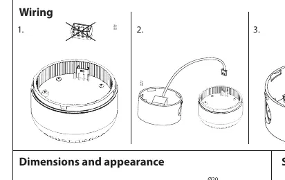
Wiring
The device supports various wiring configurations. Refer to the wiring diagram for specific connections, including:
- SW: Sound input
- GND: Ground
- NC: Not connected
- LIGHT: Strobe light input
- SOUND: Sound input
The system supports Modbus communication and relay connections (Rel. 1, Rel. 3) for failure or warning signals.
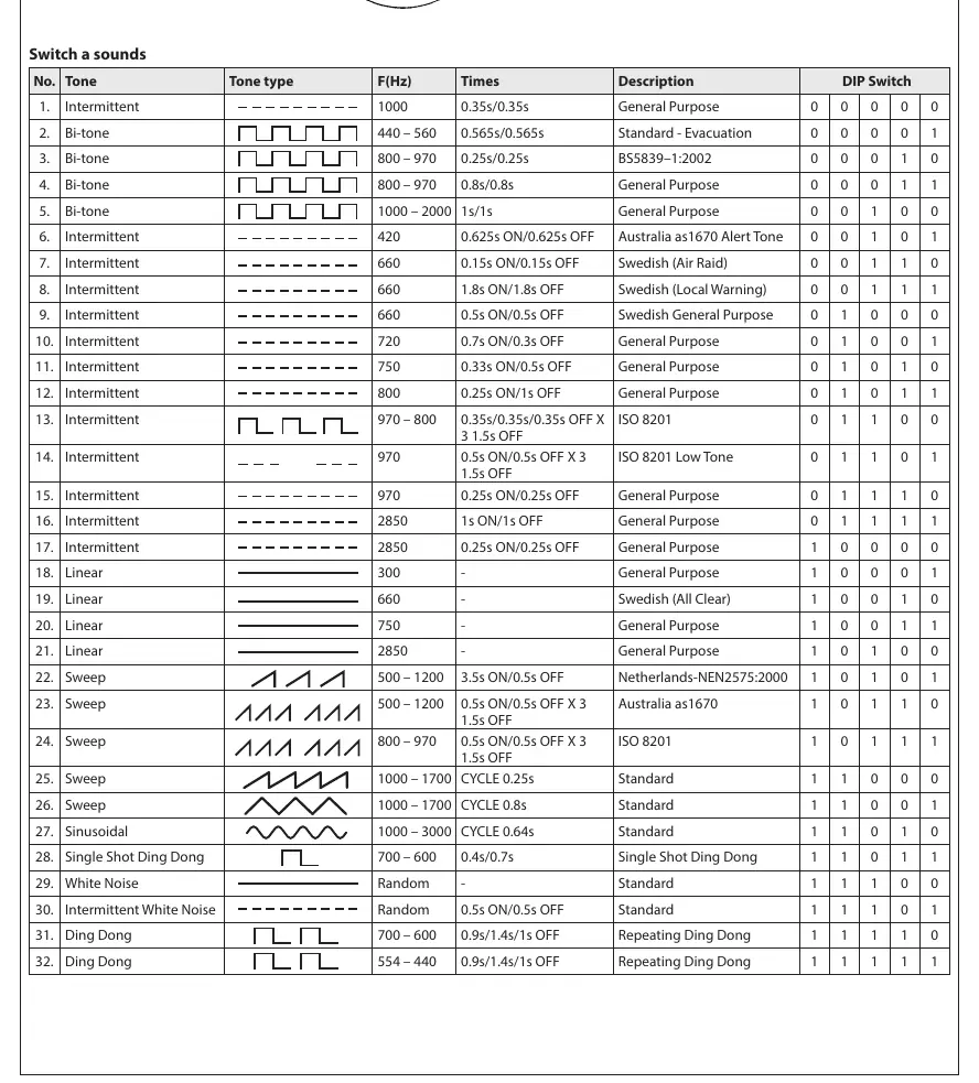
Sound settings
The device offers 32 selectable sound tones. These are configured using the DIP switches located on the device. Refer to the sound table to match the desired tone (e.g., Intermittent, Bi-tone, Sweep, Ding Dong) with the corresponding DIP switch positions (0 for OFF, 1 for ON). Volume can be adjusted by pressing the volume button for 2 seconds.
Warnings
- Installation must be done by qualified personnel.
- Do not dispose of as common waste.
- Rapid flashing lights may induce photosensitive epilepsy in certain circumstances.
- Always disconnect power before servicing.
Manufacturer information
Danfoss A/S
Practical help
Common problems
Device not sounding or flashing
Check wiring connections for SW, GND, LIGHT, and SOUND. Ensure the power supply is within the 12-24V DC range.
Incorrect sound tone
Verify the DIP switch settings against the sound table provided in the manual. Ensure switches are set to the correct ON/OFF positions.
Device failure
Check the fuse protection on the power supply line. Ensure the fuse rating is appropriate for the voltage.
Before use
- Ensure power supply is 12-24V DC.
- Verify fuse protection is installed on the power supply line.
- Ensure installation is performed by qualified personnel.
- Check that the environment is within -40 to +55 °C.
- Verify DIP switch settings for the desired sound tone.
Specs in practice
- Operating voltage
- 12–24 V DC power input required.
- Sound output
- Maximum 94 dB(A) at 1000 Hz.
Images and diagrams
- Wiring diagram: Illustrates connections for SW, GND, NC, LIGHT, and SOUND, as well as relay and Modbus connections.
- Assembly diagram: Shows the twist-lock mounting process.
- DIP switch table: Defines the 32 available sound patterns and their corresponding switch configurations.
Model compatibility
- Requires DC power supply.
- Not for use as common waste.

Manual page author
Michael Turner
Technical manual editor
Reviews PDF manuals for structure, safety notes, and practical product details so readers can find the right information quickly.