HVAC / Temperature Sensors
Installation Guide for Danfoss Link RS Room Sensor
Quick installation guide for the Danfoss Link RS Room Sensor. Includes mounting instructions, device pairing, factory reset, troubleshooting LED codes, and technical specifications.
Table of contents
Manual images
Click an image to enlargeQuick guide from the manual
The Danfoss Link RS is a battery-powered room sensor designed to measure ambient temperature and control heating. Installation involves mounting the back panel to the wall, inserting two AA batteries, and sliding the front unit onto the back panel. The device must be paired with a Danfoss Link CC Central Controller to function within the system.
Installation
The wireless transmission range is sufficient for most applications, but building obstacles may affect performance. If communication issues arise, consider using repeaters.
- Do not install the sensor in direct sunlight.
- Recommended installation height is 80-150 cm.
- In wet rooms, follow local building regulations.
- Maintain at least 50 cm distance from windows or doors that may be left open.
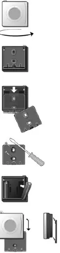
Mounting steps:
- Turn the device to access the back.
- Remove the back panel by pressing with thumbs and pulling downwards.
- Fix the back panel to the wall using screws or adhesive.
- Insert the batteries.
- Slide the front unit onto the back panel.
Adding device
The sensor is connected to the system via the Danfoss Link CC Central Controller. Refer to the Danfoss Link CC instruction manual, specifically the section on adding devices, to complete the pairing process.
Network test
After adding the device, perform a network test as described in the Danfoss Link CC manual. If prompted, go to the RS unit and press the LED button for 5 seconds to force a signal.
Factory reset
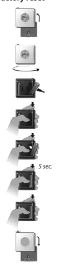
- Remove the front unit from the back panel.
- Turn the unit to access the back.
- Remove one battery.
- Press and hold the button while reinserting the battery until the LED flashes red (approx. 5 seconds).
- Replace the front unit.
Troubleshooting
The device uses LED signals to indicate status:
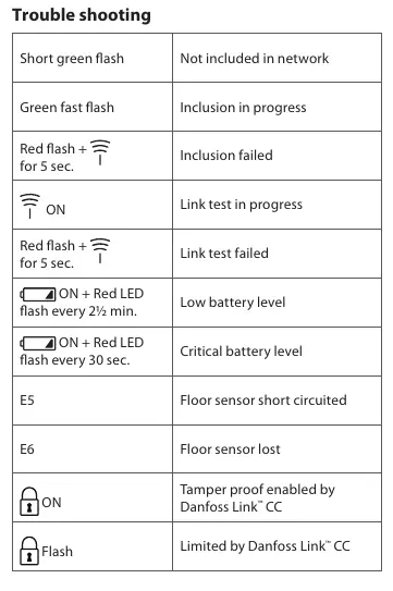
- Short green flash: Not included in network.
- Green fast flash: Inclusion in progress.
- Red flash + signal icon for 5 sec: Inclusion or link test failed.
- Signal icon ON: Link test in progress.
- ON + Red LED flash every 2.5 min: Low battery level.
- ON + Red LED flash every 30 sec: Critical battery level.
- E5: Floor sensor short circuited.
- E6: Floor sensor lost.
Technical specifications
- Battery: 2 x AA, 1.5 V Alkaline
- Battery lifetime: Up to 4-5 years
- Transmission frequency: 868.42 MHz
- Transmission range: Up to 30 m in normal buildings
- IP class: 21
- Dimensions: 75 mm x 75 mm x 24 mm
Disposal
Dispose of the device and batteries according to local regulations for electronic waste.
Manufacturer information
Danfoss A/S
Practical help
Common problems
Inclusion failed
Red flash for 5 seconds during network inclusion.
Link test failed
Red flash for 5 seconds during network test.
Low battery level
ON + Red LED flash every 2.5 minutes.
Critical battery level
ON + Red LED flash every 30 seconds.
Floor sensor errors (E5/E6)
Check floor sensor connection or for short circuits.
Before use
- Ensure you have 2 x AA batteries.
- Verify the installation location is not in direct sunlight.
- Check that the installation height is between 80-150 cm.
- Ensure the device is at least 50 cm away from windows or doors.
- Have the Danfoss Link CC Central Controller ready for pairing.
Specs in practice
- Transmission frequency
- 868.42 MHz (standard for this wireless system)
- Transmission range
- Up to 30 m in normal buildings
- Battery lifetime
- Up to 4-5 years depending on usage
Images and diagrams
- The device consists of a front unit with a display and a back panel for wall mounting.
- The LED button is located on the top of the unit for network testing and display control.
Model compatibility
- Requires Danfoss Link CC Central Controller for system integration.

Manual page author
Michael Turner
Technical manual editor
Reviews PDF manuals for structure, safety notes, and practical product details so readers can find the right information quickly.