Industrial / Motor Drives
User Manual for Danfoss CF-RU Repeater Unit
Quick guide for the Danfoss CF-RU Repeater Unit. Learn how to install, mount, perform transmission tests, and reset the device to factory settings.
Table of contents
Manual images
Click an image to enlargeQuick guide from the manual
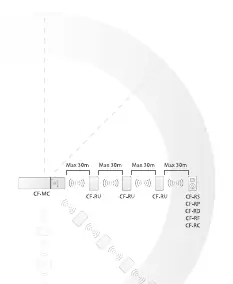
The Danfoss CF-RU Repeater Unit is designed to extend the transmission range of your heating system. It is used when system components cannot reach the Controller or when the link test is unsatisfactory. Up to three repeaters can be installed in a chain to extend the range.
Functional Overview
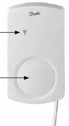
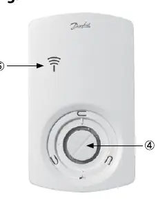
The device features a red LED indicator behind the front cover and a push button for installation and testing.
- Permanent light: ON
- No light: OFF
- Slow flashing: Flashes
- Fast flashing: Flickers
Installation
Before permanent mounting, temporarily connect the repeater to a 230V outlet near the Controller to perform the installation.
Installation in the CF2 system
- Activate Install mode on the Master Controller using the menu selection button. The Install LED will flash. Press OK to activate.
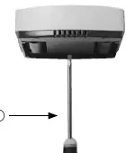
- Release the front cover of the repeater.
- Press the push button on the repeater. The LED will flicker during communication.
- If installation is satisfactory, the LED goes OFF. If not, it flashes 5 times.
Installation in the Danfoss Link system
- Install the repeater on the Danfoss Link CC by adding it as a service device (refer to the Danfoss Link CC manual).
- Release the front cover of the repeater.
- Press the push button. The LED will flicker during communication.
- If installation is satisfactory, the LED goes OFF. If not, it flashes 5 times.
Placing and Mounting
Once assigned, disconnect the repeater from the temporary power supply.
- Place the repeater between the Controller and the Room Thermostat.
- Connect it to a 230V power supply.
- Verify transmission by performing a link test from the repeater.
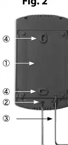
- Mount the back plate to the wall using the provided screws and wall plugs.
- Slide the repeater onto the back plate and secure it if desired by turning the lock 90 degrees with a 2mm hex key.
Transmission Test
To initiate a test from the repeater:
- Press the push button. The LED goes ON.
- If the test is satisfactory, the LED goes OFF.
- If the test is unsatisfactory, the LED flashes 5 times.
Factory Reset
- Disconnect the repeater from the power supply.
- Release the front cover.
- Press and hold the push button.
- While holding the button, plug the power supply back in.
- Release the button when the LED goes ON and then OFF.
Specifications
- Transmission frequency: 868.42MHz
- Transmission range: Up to 30m in buildings
- Max repeaters in a chain: 3
- Supply voltage: 230V AC / 4.5V
- Ambient temperature: 0-50°C
- IP class: 21
Troubleshooting
If the LED flashes 5 times, the installation or link test is unsatisfactory. Try relocating the repeater or adding additional repeaters between the Controller and the Room Thermostat.
Manufacturer information
Danfoss A/S
Practical help
Common problems
LED flashes 5 times
The installation or link test is unsatisfactory. Repeat the test or relocate the repeater to a better position.
No transmission to room/repeater
Try relocating the repeater or install up to three repeaters in a chain between the Controller and the Room Thermostat.
Before use
- Temporarily connect the repeater to a 230V outlet near the Controller for setup.
- Ensure you have access to the Master Controller or Danfoss Link CC manual.
- Verify the transmission range (up to 30m in buildings).
- Ensure the repeater is placed between the Controller and the Room Thermostat.
Specs in practice
- Transmission frequency
- 868.42MHz is the operating frequency for this wireless system.
Images and diagrams
- Fig 1: Front view showing the LED and cover.
- Fig 2: Back plate and mounting screw locations.
- Fig 3: How to release the front cover.
- Fig 4: Location of the push button for installation and testing.
- Fig 5: System diagram showing repeater placement between controller and thermostat.
Model compatibility
- Compatible with CF2 systems.
- Compatible with Danfoss Link systems.

Manual page author
David Miller
Documentation analyst
Organizes user manual content into clear summaries, with attention to model details, product context, and everyday usability.