Industrial / Communication Modules
Installation Guide for Danfoss MCD Profibus Module 175G9001
A comprehensive installation and configuration guide for the Danfoss MCD Profibus Module (175G9001). This manual covers physical mounting, wiring connections, network configuration, data structures, and troubleshooting via trip codes.
Quick answers from the manual
Quick answer
- The Danfoss MCD Profibus Module (175G9001) is installed by clipping it onto the soft starter, setting the network address via rotary switches, and connecting the Profibus network cable. Configuration requires importing the GSD file into your Master tool. p. 1, 2, 3
Key actions
- Install the module by pulling out retaining clips, aligning with the comms port, and pushing clips in. p. 1
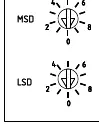
- Set the module address using the two rotary switches (MSD and LSD). p. 2
- Import the .gsd file from www.danfoss.com/drives into your Master configuration tool. p. 2
First start
- Ensure power is off, mount the module, set the address, connect the network cable, and power up. p. 1, 2
Problems and fixes
Bus Status LED is OFF
Check network connection; indicates no connection, offline, or data exchange failure.
p. 4Maintenance and reset
- If a communications failure occurs, the soft starter may trip. Reset the soft starter once communication is restored. p. 4
Technical specifications
| Parameter | Value | Meaning | Pages |
|---|---|---|---|
| Dimensions | 40 mm x 166 mm x 90 mm | Physical size of the module | p. 11 |
| Weight | 250 g | Weight of the module | p. 11 |
| Power Consumption | 35 mA at 24 VDC | Maximum steady state power consumption | p. 11 |
Where to find it in the PDF
- Installation p. 1
- Configuration p. 2
- Connection p. 3
- Specifications p. 11
Table of contents
Manual images
Click an image to enlargeQuick Guide
The Danfoss MCD Profibus Module (175G9001) allows for remote control and monitoring of soft starters via a Profibus network. Key steps include physical installation, setting the module address, configuring the Master tool with the GSD file, and establishing electrical connections.
Physical Installation
Before installing or removing the module, ensure all mains and control voltage are disconnected from the soft starter to prevent equipment damage.
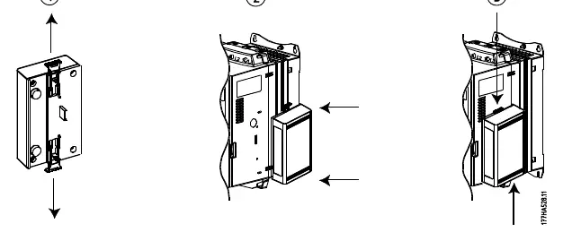
- Mounting: Pull out the top and bottom retaining clips on the module. Align the module with the comms port slot on the soft starter. Push in the retaining clips to secure the module.
- Removal: Disconnect all field wiring. Pull out the retaining clips and remove the module from the soft starter.
Configuration
To configure the module:
- Import the latest .gsd file into your Master configuration tool (available at www.danfoss.com/drives).
- Set the two rotary switches on the module to match the address set in your Master configuration tool.
- The module automatically detects the network data rate.
Connection
The module connects to the Profibus network via a standard 9-pin Sub-D connector. It can be powered via the network cable or an external 24 VDC supply.
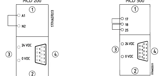
- MCD 200: A link must be fitted across terminals A1-N2 on the soft starter for serial commands.
- MCD 500: The soft starter must be in Auto On mode, and links must be fitted to terminals 17, 18 and 25, 18.
LED Indicators
- Power Status (Red): OFF = Module not powered up; ON = Module powered up and ready.
- Bus Status (Green): OFF = No connection/offline/failure; ON = Module online and in data exchange state.
Data Structures
The module supports three operating modules via the GSD file:
- Basic Module: Start/stop and limited status monitoring.
- Extended Module: Includes motor current and temperature data.
- Parameter Upload/Download Module: Allows reading/writing soft starter parameters (MCD 500 only).
Troubleshooting
The module reports trip codes via the diagnostic telegram. Common trip codes include:
- 1: Excess start time
- 2: Motor overload
- 3: Motor thermistor
- 6: Phase sequence
- 15/16: Communication failure
Specifications
- Dimensions: 40 mm (W) x 166 mm (H) x 90 mm (D)
- Weight: 250 g
- Protection: IP20
- Power Consumption: 35 mA at 24 VDC
- Network Address Range: 0 to 99
Official resources from the manual
Manufacturer information
Danfoss A/S
Practical help
Common problems
Communication failure
Check network connection and Bus Status LED. If communication fails, the Bus Status LED will go off.
Invalid data request
Ensure the data request number is valid (1-14). An invalid request will set the invalid data request bit to 1.
Soft starter trip
Check the trip code in the diagnostic telegram or monitoring data and refer to the Trip Codes table in the manual.
Before use
- Import the latest .gsd file into your Master configuration tool.
- Ensure mains and control power are disconnected before installation.
- Set the rotary address switches to match the Master configuration.
- Verify wiring links for MCD 200 or MCD 500 as required.
- Ensure the network connector is securely inserted.
Images and diagrams
- Physical installation diagram shows how to use the retaining clips to attach the module to the soft starter.
- Address switch diagram illustrates the MSD and LSD rotary switches for setting the network address.
- Wiring diagrams show the pinout for the 9-pin Sub-D connector and terminal links for MCD 200/500.
Model compatibility
- MCD 200 requires a link across terminals A1-N2.
- MCD 500 requires links on terminals 17, 18 and 25, 18 and must be in Auto On mode.
- Parameter Upload/Download module is only applicable to MCD 500 soft starters.

Manual page author
Michael Turner
Technical manual editor
Reviews PDF manuals for structure, safety notes, and practical product details so readers can find the right information quickly.