Industrial / Pressure Switches
Installation and User Guide for Danfoss ECA 73 M-Bus Combi Module
A comprehensive installation and configuration guide for the Danfoss ECA 73 M-Bus combi module. This manual covers mounting, wiring, parameter settings for the ECL Comfort 300S controller, and troubleshooting procedures.
Quick answers from the manual
Quick answer
- The ECA 73 M-Bus combi module allows the ECL Comfort 300S controller to read flow or energy data from connected heat meters via M-Bus or pulse communication. p. 3
Key actions
- Mounting the module p. 6
- Scanning M-Bus addresses p. 11
First start
- Ensure the module is seated, connect sensors/bus, and configure parameters 114/115. p. 4, 6, 8
Problems and fixes
Parameter 110 reports 0
Check connections, power supply, and heat meter setup.
p. 14Technical specifications
| Parameter | Value | Meaning | Pages |
|---|---|---|---|
| Communication speed | 300 b/s | M-Bus communication speed | p. 4 |
Where to find it in the PDF
- Introduction p. 1, 3
- Configuration p. 3, 4, 5, 6
- Troubleshooting p. 12, 14, 15
Table of contents
Manual images
Click an image to enlargeQuick guide from the manual
The ECA 73 M-Bus combi module enables the ECL Comfort 300S controller to read measured values of flow or energy consumption from connected heat meters. It supports M-Bus and pulse communication. The module is powered by the ECL Bus and requires an outdoor temperature sensor connected to the ECL Comfort controller to function.
Mounting and wiring
The module is designed to be installed directly into the ECL Comfort controller socket.
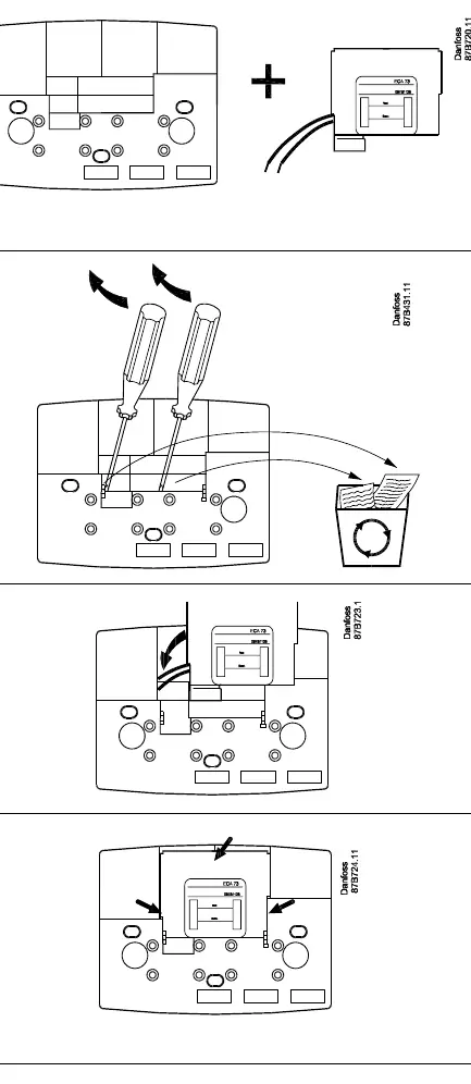
- Mounting: Remove the knockout cover on the controller socket using a screwdriver. Feed cables through the opening and insert the module base until it clicks into place.
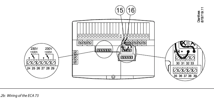
- Wiring: Connect system device bus cables to terminals 15 and 16. Sensor connections use terminals 30-33. M-Bus and pulse inputs use terminals 35-37.
- Cable specifications: Use twisted pair telephone cable (JYStY) with a maximum length of 50m for communication.
Configuration and parameters
Service parameters are accessed via the ECL Comfort front panel. Key parameters include:
- Parameter 115: Determines the unit and range of flow/energy measurement.
- Parameter 114: Defines the amount of water/energy per pulse (set to OFF if not using pulse communication).
- Parameter 112: Time constant for integral control of flow/energy limiting.
- Parameter 113: Time constant for digital filtering of input data.
- Parameter A3: Used to scan M-Bus addresses (set to ON to initiate, takes 15 minutes).
- Parameter A2: Used to swap M-Bus addresses if necessary.
Troubleshooting
If the system is not reporting data correctly:
- Check connections: Ensure cables are undamaged and properly connected to both the controller and the heat meter.
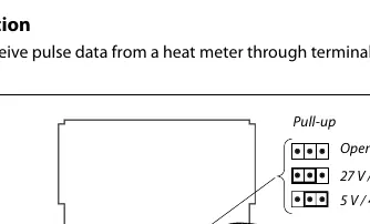
- Verify power: If using M-Bus, ensure the ECA 73 is supplied with external power if a 27V pull-up is required.
- Check seating: Ensure the module is properly seated in the connector.
- Verify software: Ensure the ECL Comfort 300S is running software version 1.10 or later.
Dismounting
The product should be dismantled and components sorted into groups before recycling or disposal, following local regulations.
Manufacturer information
Danfoss A/S
Practical help
Common problems
ECL Comfort reports 0 for parameter 110
Check if the heat meter is properly connected and set up. Ensure the ECA 73 is powered (for M-Bus) and properly seated in the connector.
Data discrepancy in pulse communication
Discrepancies at low flow/energy are due to the calculation method. Ensure values are within the expected range.
Service parameters not accessible
Ensure the ECA 73 module is properly seated in the connector.
Before use
- Verify ECL Comfort 300S software version 1.10 or later
- Ensure outdoor temperature sensor is connected to the ECL Comfort controller
- Determine if M-Bus or Pulse communication is required
- Ensure heat meter is set to 300 baud and a unique address between 1 and 250
Specs in practice
- Parameter 115
- Determines the unit and range of flow/energy measurement.
- Parameter 114
- Determines the amount of water/energy that one pulse signifies.
- Parameter 112
- Time constant for integral control (high value = fast control).
- Parameter 113
- Time constant for digital filtering (high value = high filtering).
Images and diagrams
- Figure 1.3.3a: Pulse input configuration showing pull-up resistor options.
- Figure 2.2b: Terminal connections for relays, sensors, and M-Bus/Pulse.
- Figure 2.5.2a: Principle of flow/energy limitation based on outdoor temperature.
Model compatibility
- Compatible with ECL Comfort 300S series (software version 1.10+).
- Compatible with various heat meters (Infocal 5, MULTICAL III, etc.).
- Max 2 ECA modules can be connected.
- Slave addresses 7, 8, 9, and 14 must not be used in master/slave systems.

Manual page author
Michael Turner
Technical manual editor
Reviews PDF manuals for structure, safety notes, and practical product details so readers can find the right information quickly.